


19
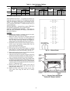
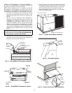
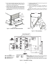
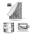
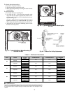
6. Insert the hood divider between the hood sides. See
Fig. 24 and 25. Secure hood divider with 2 screws on
each hood side. The hood divider is also used as the bot-
tom filter rack for the aluminum filter.
7. Open the filter clips which are located underneath the
hood top. Insert the aluminum filter into the bottom filter
rack (hood divider). Push the filter into position past the
open filter clips. Close the filter clips to lock the filter into
place. See Fig. 25.
8. Caulk the ends of the joint between the unit top panel and
the hood top. See Fig. 23.
9. Replace the filter access panel.
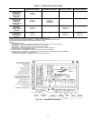
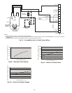
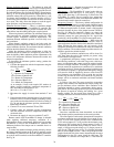
10. Install all EconoMi$er IV accessories. EconoMi$er IV
wiring is shown in Fig. 26. EconoMi$er2 wiring is shown
in Fig. 27.
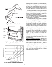
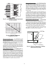
Barometric flow capacity is shown in Fig. 28. Outdoor air
leakage is shown in Fig. 29. Return air pressure drop is shown
in Fig. 30.
B
TOP
PANEL
INDOOR COIL
ACCESS PANEL
24 9/16”
SCREW
HOOD DIVIDER
LEFT
HOOD
SIDE
40 3/8”
Fig. 24 — Outdoor-Air Hood Construction
22 1/4”
DIVIDER
BAROMETRIC
RELIEF
CLEANABLE
ALUMINUM
FILTER
FILTER
HOOD
FILTER
CLIP
OUTSIDE
AIR
Fig. 25 — Filter Installation
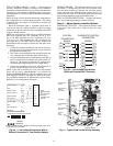
FOR OCCUPANCY CONTROL
REPLACE JUMPER WITH
FIELD-SUPPLIED TIME CLOCK
LEGEND
DCV— Demand Controlled Ventilation
IAQ — Indoor Air Quality
LA — Low AmbientLockout Device
OAT — Outdoor-Air Temperature
POT— Potentiometer
RAT— Return-Air Temperature
Potentiometer Defaults Settings:
Power Exhaust Middle
Minimum Pos. Fully Closed
DCV Max. Middle
DCV Set Middle
Enthalpy C Setting
NOTES:
1. 620 ohm, 1 watt 5% resistor should be removed only when using differential
enthalpy or dry bulb.
2. If a separate field-supplied 24 v transformer is used for the IAQ sensor power
supply, it cannot have the secondary of the transformer grounded.
3. For field-installed remote minimum position POT, remove black wire jumper
between P and P1 and set control minimum position POT. to the minimum
position.
Fig. 26 — EconoMi$er IV Wiring