


45
Heating — To start the unit, turn on the main power supply.
Set the thermostat at HEAT position at a setting above room
temperature, the fan at AUTO position.
The first stage of the thermostat energizes the indoor-fan
motor, compressor, and outdoor fan; the second stage energizes
electric heater elements, if installed. Check the heating effects
at the air supply grille(s).
If the accessory electric heaters do not energize, reset limit
switch (located on indoor-fan scroll) by pressing the button
located between terminals on the switch.
TO SHUT OFF UNIT — Set the system selector switch at
OFF position. Resetting the heating selector lever below room
temperature temporarily shuts the unit off until the space
temperature falls below the thermostat setting.
Safety Relief — A soft solder joint on the suction line at
the loss-of-charge/low-pressure fitting provides pressure relief
under abnormal temperature and pressure conditions.
Ventilation (Continuous Fan) — Set the fan and system
selector switches at ON and OFF positions, respectively. The in-
door fan operates continuously to provide constant air circulation.
Operating Sequence
COOLING, UNITS WITHOUT ECONOMIZER — When
thermostat calls for cooling, terminals G and Y1 are energized.
The indoor-fan contactor (IFC), reversing valve solenoid
(RVS1) and compressor contactor no. 1 (C1) are energized and
indoor-fan motor, compressor no. 1, and outdoor fan starts. The
outdoor-fan motor(s) run continuously while unit is cooling. If
the thermostat calls for a second stage of cooling by energizing
Y2, compressor contactor no. 2 (C2) and reversing valve sole-
noid (RVS2) are energized and compressor no. 2 starts.
HEATING, UNITS WITHOUT ECONOMIZER — Upon a
request for heating from the space thermostat, terminal W1 will
be energized with 24 v. The IFC, outdoor-fan contactor (OFC),
C1, and C2 will be energized. The reversing valves switch po-
sition and the indoor fan, outdoor fan, compressor no. 1, and
compressor no. 2 are energized.
If the space temperature continues to fall while W1 is ener-
gized, W2 will be energized with 24 v, and the heater contac-
tor(s) (HC) will be energized, which will energize the electric
heater(s).
When the space thermostat is satisfied, W2 will be deener-
gized first, and the electric heater(s) will be deenergized.
Upon a further rise in space temperature, W1 will be
deenergized, and the reversing valve solenoids (RVS1 and
RVS2) will be energized.
COOLING, UNITS WITH ECONOMI$ER IV — When free
cooling is not available, the compressors will be controlled by
the zone thermostat. When free cooling is available, the
outdoor-air damper is modulated by the EconoMi$er IV con-
trol to provide a 50 to 55 F supply-air temperature into the
zone. As the supply-air temperature fluctuates above 55 or
below 50 F, the dampers will be modulated (open or close)
to bring the supply-air temperature back within set point limits.
For EconoMi$er IV operation, there must be a thermostat
call for the fan (G). This will move the damper to its minimum
position during the occupied mode.
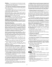
Above 50 F supply-air temperature, the dampers will modu-
late from 100% open to the minimum open position. From 50 F
to 45 F supply-air temperature, the dampers will maintain at
the minimum open position. Below 45 F the dampers will be
completely shut. As the supply-air temperature rises, the damp-
ers will come back open to the minimum open position once
the supply-air temperature rises to 48 F.
If optional power exhaust is installed, as the outdoor-air
damper opens and closes, the power exhaust fans will be ener-
gized and deenergized.
If field-installed accessory CO
2
sensors are connected to the
EconoMi$er IV control, a demand controlled ventilation strate-
gy will begin to operate. As the CO
2
level in the zone increases
above the CO
2
set point, the minimum position of the damper
will be increased proportionally. As the CO
2
level decreases
because of the increase in fresh air, the outdoor-air damper will
be proportionally closed. Damper position will follow the high-
er demand condition from DCV mode or free cooling mode.
Damper movement from full closed to full open (or vice
versa) will take between 1
1
/
2
and 2
1
/
2
minutes.
If free cooling can be used as determined from the appropri-
ate changeover command (switch, dry bulb, enthalpy curve,
differential dry bulb, or differential enthalpy), a call for cooling
(Y1 closes at the thermostat) will cause the control to modulate
the dampers open to maintain the supply-air temperature set
point at 50 to 55 F.
As the supply-air temperature drops below the set point
range of 50 to 55 F, the control will modulate the outdoor-air
dampers closed to maintain the proper supply-air temperature.
HEATING, UNITS WITH ECONOMI$ER IV — When the
room temperature calls for heat, the heating controls are ener-
gized as described in the Heating, Units Without Economizer
section. When the thermostat is satisfied, the economizer
damper moves to the minimum position.
COOLING, UNITS WITH ECONOMI$ER2, PREMIER-
LINK™ CONTROL AND A THERMOSTAT — Whenfree
cooling is not available, the compressors will be controlled by
the PremierLink control in response to the Y1 and Y2 inputs
from the thermostat.
The PremierLink control will use the following information
to determine if free cooling is available:
• Indoor fan has been on for at least 30 seconds.
• The SPT, SAT, and OAT inputs must have valid readings.
• OAT must be less than 75 F.
• OAT must be less than SPT.
• Enthalpy must be LOW (may be jumpered if an enthalpy
sensor not available).
• Economizer position is NOT forced.
Pre-cooling occurs when the is no call from the thermostat
except G. Pre-cooling is defined as the economizer modulates
to provide 70 F supply air.
When free cooling is available the PremierLink control will
control the compressors and economizer to provide a supply-
air temperature determined to meet the Y1 and Y2 calls from
the thermostat using the following three routines. The three
control routines are based on OAT, where:
SASP = Supply Air Set Point
DXCTLO = Direct Expansion Cooling Lockout Set Point
Routine 1
—(OAT<DXCTLO)
• Y1 energized — economizer maintains a SASP =
(SATLO1 + 3).
• Y2 energized — economizer maintains a SASP =
(SATLO2 + 3).
Routine 2
—(DXCTLO<OAT<68F)
• If only Y1 energized, the economizer maintains a SASP
=(SATLO1+3).
• If SAT > SASP + 5 and economizer position > 80%,
economizer will go to minimum position for 3 minutes or
until SAT > 68 F.
• First stage of mechanical cooling will be energized.
• Integrator resets.
• Economizer opens again and controls to current SASP
after stage one on for 90 seconds.
• With Y1 and Y2 energized Economizer maintains an
SASP = SATLO2 + 3.