


13
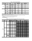
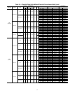
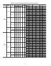
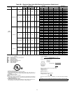
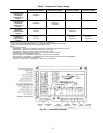
Table 4 — Heat Anticipator Settings
*kW is based on 240, 480, or 575 v.
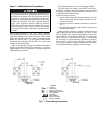
CONVENIENCE OUTLET — An optional convenience out-
let provides power for rooftop use. For maintenance personnel
safety, the convenience outlet power is off when the unit dis-
connect is off. Adjacent unit outlets may be used for service
tools. An optional “Hot Outlet” is available from the factory as
a special order item.
NOVAR CONTROLS — Optional Novar controls (ETM 3051)
are available for replacement or new construction jobs.
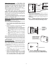
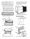
MANUAL OUTDOOR-AIR DAMPER — The outdoor-air
hood and screen are attached to the basepan at the bottom of
the unit (for shipping).
Assembly:
1. Determine the amount of ventilation required for build-
ing. Record the amount for use in Step 8.
2. Remove the filter access panel by raising the panel and
swinging it outward. The panel is now disengaged from
the track and can be removed. No tools are required to re-
move the filter access panel. Remove the outdoor-air
opening panel. Save the panels and screws. See Fig. 11.
3. Separate the hood and screen from the basepan by remov-
ing the screws and brackets securing them. Save all
screws and discard the brackets.
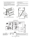
4. Replace the outdoor air opening panel.
5. Place the hood on the front of the outdoor air opening
panel. See Fig. 12 for hood details. Secure the top of the
hood with the 6 screws removed in Step 3. See Fig. 13.
6. Remove and save the 8 screws (4 on each side) from the
sides of the manual outdoor-air damper.
7. Align the screw holes on the hood with the screw holes
on the side of the manual outdoor-air damper. See Fig. 12
and 13. Secure the hood with the 8 screws from Step 6.
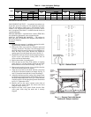
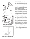
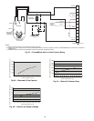
8. Adjust the minimum position setting of the damper blade
by adjusting the manual outdoor-air adjustment screws on
the front of the damper blade. See Fig. 11. Slide the blade
vertically until it is in the appropriate position determined
by Fig. 14. Tighten the screws.
9. Remove and save the screws currently on the sides of
hood. Insert the screen. Secure the screen to the hood
using the screws. See Fig. 13.
10. Replace the filter access panel. Ensure that the filter
access panel slides along the tracks and is securely
engaged.
UNIT
UNIT VOLTAGE
208/230 460 575
Heater
kW*
Configuration
Heater
kW*
Configuration
Heater
kW*
Configuration
1-Stage
2-Stage
1-Stage
2-Stage
1-Stage
2-Stage
Stage 1 Stage 2 Stage 1 Stage 2 Stage 1 Stage 2
50TFQ
10.4, 16.0 0.3 NA NA
13.9, 16.5
27.8, 33.0
0.3 NA NA 17.0, 34.0 0.3 NA NA
24.8, 32.0 0.6 0.3 0.3
42.4, 50.0 0.9 0.6 0.3 41.7, 50.0 0.6 0.3 0.3 51.0 0.6 0.3 0.3
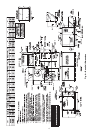
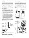
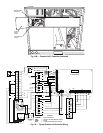
Fig. 10 — Defrost Board
SCREWS
(SIDE)
MANUAL
OUTDOOR-AIR
ADJUSTMENT
SCREWS
DAMPER
BLADE
FILTER
ACCESS
PANEL
OUTDOORAIR
OPENING
PANEL
Fig. 11 — Damper Panel with Manual
Outdoor-Air Damper Installed