


44
PRE-START-UP
Proceed as follows to inspect and prepare the unit for initial
start-up:
1. Remove all access panels.
2. Read and follow instructions on all WARNING, CAU-
TION, and INFORMATION labels attached to or
shipped with unit.
3. Make the following inspections:
a. Inspect for shipping and handling damages such
as broken lines, loose parts, or disconnected wires.
b. Inspect for oil at all refrigerant tubing connections
and on the unit base. Detecting oil generally indi-
cates a refrigerant leak. Leak-test all refrigerant
tubing connections using an electronic leak detec-
tor, halide torch, or liquid-soap solution.
c. Inspect all field-wiring and factory-wiring con-
nections. Be sure that connections are completed
and tight. Ensure that electrical wires do not
contact refrigerant tubing.
d. Inspect the coil fins. If damaged during shipping
and handling, carefully straighten the fins with a
fin comb.
4. Verify the following conditions:
a. Make sure that the outdoor-fan blades are
correctly positioned in the fan orifice. Refer to
Outdoor-Fan Adjustment section on page 48 for
more details.
b. Make sure that an air filter(s) is in place.
c. Make sure that the condensate drain trap is filled
with water to ensure proper drainage.
d. Make sure that all tools and miscellaneous loose
parts have been removed.
START-UP
Unit Preparation —
Make sure that the unit has been
installed in accordance with installation instructions and
applicable codes.
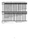
Return-Air Filters — Make sure that the correct filters
are installed in the unit (see Table 1). Do not operate the unit
without return-air filters.
Outdoor-Air Inlet Screen — The outdoor-air inlet screen
must be in place before operating the unit.
Compressor Mounting — Compressors are internally
spring mounted. Do not loosen or remove the compressor hold-
down bolts.
Internal Wiring — Check all electrical connections in
unit control boxes; tighten as required.
Refrigerant Service Ports — Each refrigerant system
has 3 Schrader-type service gage ports: One on the suction line,
one on the cooling mode liquid line, and one on the compressor
discharge line. Be sure that the caps on the ports are tight.
The port on the cooling mode liquid line and one port on the
discharge line have protective devices installed on them.
HIGH FLOW REFRIGERANT VALVES — Two high flow
valves may be located on the hot gas tube coming out of the
compressor and the suction tube going into the compressor.
Large black plastic caps identify these valves with O-rings
inside screwing the cap and onto a brass body. No field access
to these valves is available at this time. Ensure the plastic caps
remain on the valves and are tight or the possibility of refriger-
ant leakage could occur.
Compressor Rotation — It is important to be certain
that the scroll compressor (size 012 only) is rotating in the
proper direction. To determine whether or not the compressor
is rotating in the proper direction:
1. Connect service gages to the suction and discharge pres-
sure fittings.
2. Energize the compressor.
3. The suction pressure should drop and the discharge pres-
sure should rise, as is normal on any start-up.
If the suction pressure does not drop and the discharge pres-
sure does not rise to normal levels:
1. Note that the indoor fan is probably also rotating in the
wrong direction.
2. Turn off power to the unit and tag disconnect.
3. Reverse any two of the unit power leads.
4. Turn on power to the unit. Re-energize compressor.
The suction and discharge pressure levels should now move
to their normal start-up levels.
NOTE: When the compressor is rotating in the wrong
direction, the unit makes more noise and does not provide
heating/cooling.
Cooling — To start the unit, turn on main power supply. Set
the system selector switch at COOL position and the fan switch
at AUTO position. Adjust the thermostat to a setting below room
temperature. The compressor starts on closure of the contactor.
Check the unit charge. Refer to Refrigerant Charge section
on page 48.
Reset the thermostat at a position above room temperature.
The compressor will shut off.
TO SHUT OFF UNIT — Set the system selector switch at
OFF position. Resetting the thermostat at a position above
room temperature shuts the unit off temporarily until the space
temperature exceeds the thermostat setting.
The compressor restart is accomplished by manual reset at
the thermostat by turning the selector switch to OFF position
and then ON position.
Failure to observe the following warnings could result in
serious personal injury:
1. Follow recognized safety practices and wear protec-
tive goggles when checking or servicing refrigerant
system.
2. Do not operate the compressor or provide any electric
power to the unit unless the compressor terminal
cover is in place and secured.
3. Do not remove the compressor terminal cover until all
electrical sources are disconnected.
4. Relieve all pressure from the system before touching
or disturbing anything inside the compressor terminal
box if a refrigerant leak is suspected around the com-
pressor terminals. Use accepted methods to recover
refrigerant.
5. Never attempt to repair a soldered connection while
the refrigerant system is under pressure.
6. Do not use a torch to remove any component. The
system contains oil and refrigerant under pressure. To
remove a component, wear protective goggles and
proceed as follows:
a. Shut off electrical power to the unit and tag
disconnect.
b. Relieve all pressure from the system using both
the high and low-pressure ports. Use accepted
methods to recover refrigerant.
c. Cut the component connection tubing with tubing
cutter, and remove the component from the unit.
d. Carefully unsweat the remaining tubing stubs
when necessary. Oil can ignite when exposed
to a torch flame.