


17
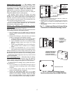
Enthalpy Sensors and Control
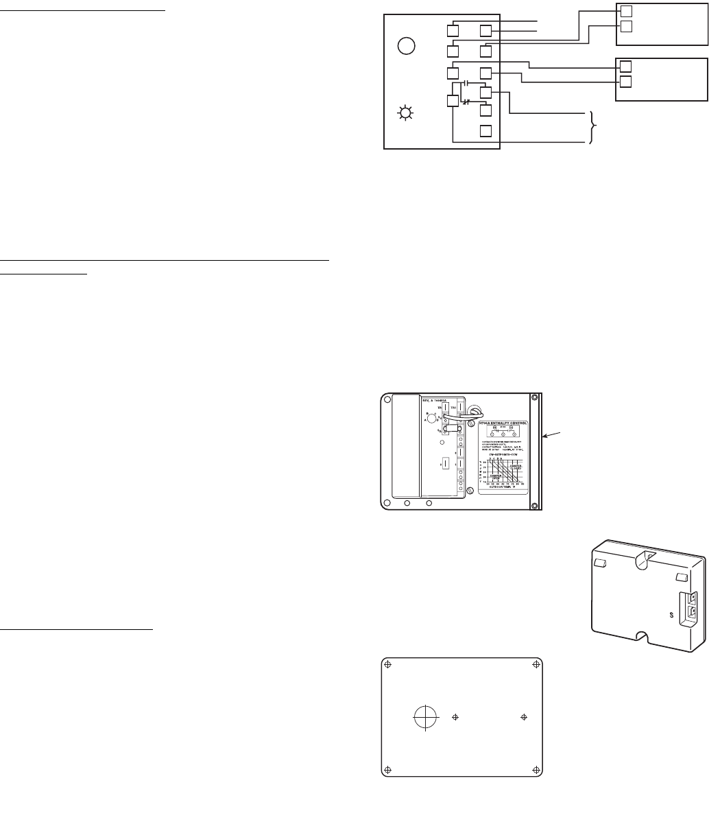
— The enthalpy control
(HH57AC077) is supplied as a field-installed accessory to be
used with the economizer damper control option. The outdoor
air enthalpy sensor is part of the enthalpy control. The separate
field-installed accessory return air enthalpy sensor
(HH57AC078) is required for differential enthalpy control.
NOTE: The enthalpy control must be set to the “D” setting for
differential enthalpy control to work properly.
The enthalpy control receives the indoor and return
enthalpy from the outdoor and return air enthalpy sensors and
provides a dry contact switch input to the PremierLink™
controller. Locate the controller in place of an existing econo-
mizer controller or near the actuator. The mounting plate may
not be needed if existing bracket is used.
A closed contact indicates that outside air is preferred to the
return air. An open contact indicates that the economizer
should remain at minimum position.
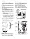
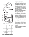
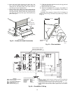
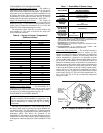
Outdoor Air Enthalpy Sensor/Enthalpy Controller
(HH57AC077) — To wire the outdoor air enthalpy sensor,
perform the following (see Fig. 17 and 18):
NOTE: The outdoor air sensor can be removed from the back
of the enthalpy controller and mounted remotely.
1. Use a 4-conductor, 18 or 20 AWG cable to connect the
enthalpy control to the PremierLink controller and power
transformer.
2. Connect the following 4 wires from the wire harness
located in rooftop unit to the enthalpy controller:
a. Connect the BRN wire to the 24 vac terminal (TR1)
on enthalpy control and to pin 1 on 12-pin harness.
b. Connect the RED wire to the 24 vac GND terminal
(TR) on enthalpy sensor and to pin 4 on 12-pin
harness.
c. Connect the GRAY/ORN wire to J4-2 on Premier-
Link controller and to terminal (3) on enthalpy
sensor.
d. Connect the GRAY/RED wire to J4-1 on Premier-
Link controller and to terminal (2) on enthalpy sensor.
NOTE: If installing in a Carrier rooftop, use the two gray wires
provided from the control section to the economizer to connect
PremierLink controller to terminals 2 and 3 on enthalpy sensor.
If NOT using Carrier equipment, wires may need to be field
supplied and installed.
Return Air Enthalpy Sensor
— Mount the return-air enthalpy
sensor (HH57AC078) in the return-air duct. The return air
sensor is wired to the enthalpy controller (HH57AC077). The
outdoor enthalpy changeover set point is set at the controller.
To wire the return air enthalpy sensor, perform the follow-
ing (see Fig. 17):
1. Use a 2-conductor, 18 or 20 AWG, twisted pair cable to
connect the return air enthalpy sensor to the enthalpy
controller.
2. At the enthalpy control remove the factory-installed
resistor from the (SR) and (+) terminals.
3. Connect the field-supplied RED wire to (+) spade
connector on the return air enthalpy sensor and the (SR+)
terminal on the enthalpy controller. Connect the BLK
wire to (S) spade connector on the return air enthalpy
sensor and the (SR) terminal on the enthalpy controller.
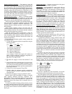
BRACKET
+
C7400A1004
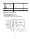
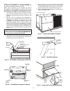
Fig. 18 — Differential Enthalpy Control,
Sensor and Mounting Plate (33AMKITENT006)
HH57AC077
ENTHALPY
CONTROL AND
OUTDOOR AIR
ENTHALPY
SENSOR
HH57AC078 ENTHALPY
SENSOR (USED WITH
ENTHALPY CONTROL
FOR DIFFERENTIAL
ENTHALPY OPERATION)
MOUNTING PLATE
LED
A
B
C
D
TR TR1
SO
SR
2
3
1
+
+
BRN
RED
GRAY/ORN
GRAY/RED
WIRE HARNESS
IN UNIT
BLK
RED
S
+
(RETURNAIR
ENTHALPY
SENSOR)
S
+
(OUTDOOR
AIR
ENTHALPY
SENSOR)
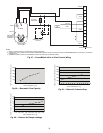
ENTHALPY CONTROLLER
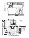
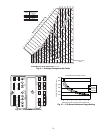
NOTES:
1. Remove factory-installed jumper across SR and + before con-
necting wires from return air sensor.
2. Switches shown in high outdoor air enthalpy state. Terminals 2
and 3 close on low outdoor air enthalpy relative to indoor air
enthalpy.
3. Remove sensor mounted on back of control and locate in out-
door airstream.
Fig. 17 — Outdoor and Return Air Sensor Wiring
Connections for Differential Enthalpy Control