


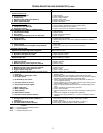

CONDENSER-FAN MOTOR PROTECTION — Each
condenser-fan motor is internally protected against over-
temperature. They are also protected against a severe over-
current condition by manual reset, calibrated trip, magnetic
circuit breakers on a common circuit.As with the circuitbreak-
ers, do not bypass connections or increase breaker size to
correct trouble. Determine the cause and correct it before
resetting the breaker.
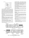
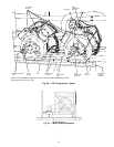
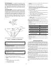
HIGH- AND LOW-PRESSURE SWITCHES — See Fig. 60
for compressor mounting locations. Settings for these switches
are shown in Table 33. If either switch trips, that refrigerant
circuit will be automatically locked out by the controls. To
reset, interrupt control power.
NOTE: When a pressure transducer is used, the low pres-
sure trip point is the same as the low-pressure switch.
Variable Frequency Drive (VFD)
SUPPLY FAN VFD — The optional supply fan VFD is lo-
cated in the auxiliary control box. Wiring should only be
performed by qualified personnel. All parameters have been
factory set. Do not change parameters unless necessary.
The VFD can be easily damaged by static electricity. Use
proper electrostatic discharge procedures when handling the
controls of the VFD.
Never connect main circuit output terminals T1, T2, and
T3 toAC main circuit power supply.Always ground the VFD
using the designated ground terminal. Refer to the VFD tech-
nical manual for more information.
The VFD can indicate faults and alarms. Ablinking alarm
condition is a warning that a trouble condition will occur or
that there is a problem in the external circuitry. The VFD
will continue to operate during an alarm condition. Alarm
conditions are not entered into the fault register.
A steady fault indicator is displayed when the VFD fault
relay has tripped. The motor will coast to a stop, and a fault
signal is output is present.
Refer to the VFD technical manual for more information
on alarms and faults.
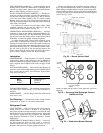
EXHAUST FAN VFD —The optional exhaust fan VFD con-
sists of an exhaust fan, motor, VFD, and pressure transducer.
All components (except the tranducer) are located in the re-
turn air section of the 48/50MP, through the hinged access
door. The BP transducer is located in the auxiliary control
box. Wiring should only be performed by qualified person-
nel. All parameters have been factory set. Do not change pa-
rameters unless necessary.
The VFD can be easily damaged by static electricity. Use
proper electrostatic discharge procedures when handling the
controls of the VFD.
Never connect main circuit output terminals T1, T2, and
T3 toAC main circuit power supply.Always ground the VFD
using the designated ground terminal. Refer to the VFD tech-
nical manual for more information.
The VFD can indicate faults and alarms. Ablinking alarm
condition is a warning that a trouble condition will occur or
that there is a problem in the external circuitry. The VFD
will continue to operate during an alarm condition. Alarm
conditions are not entered into the fault register.
A steady fault indicator is displayed when the VFD fault
relay has tripped. The motor will coast to a stop, and a fault
signal is output is present.
Refer to the VFD technical manual for more information
on alarms and faults.
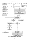
DISPLAYING FAULT SEQUENCE — Whenever the fault
relay trips and shuts down the VFD, the display code of the
fault that caused the trip will be displayed until RESET
is
pressed. The fault code will also be entered into the fault
register. The register retains, in sequence, the last 3 fault codes.
A newly occurring fault code will not change the fault reg-
ister if it a recurrence of the most recently entered fault. The
contents of the register can be displayed by performing the
following steps:
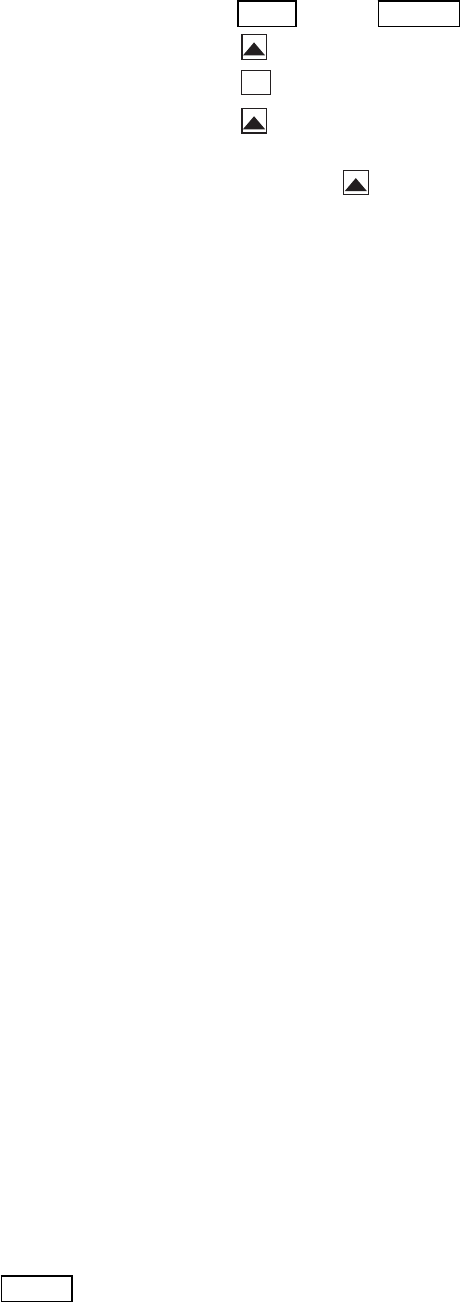
1. Press DSPL
until the MONTR LED is on.
2. Press until U-09 is displayed.
ENTER
3. Press . The current fault code will be displayed.
4. Press . The display will indicate that this is the first
code in the memory register.
5. Continue to press to display the other codes in the
fault resister. After the last code has been displayed, the
sequence will return to the first code.
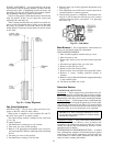
Control Modules — The standard PSIO1 and optional
PSIO2 (processor modules) and standard DSIO1 and DSIO2
(high-voltage relay modules) all perform continuous diag-
nostic evaluations of the hardware condition. Proper opera-
tion of these modules is indicated by 2 light-emitting diodes
(LED) on the front surface of the DSIO modules and on the
top horizontal surface of the PSIO modules.
RED LED — Blinking continuously ata3to5second rate
indicates proper operation. Lit continuously indicates a prob-
lem requiring replacement of the module. Off continuously
indicates the power supply should be checked. If there is no
input power, check the fuses. If a fuse is bad, check for shorted
secondary of the transformer or a bad module.
GREEN LED — On a PSIO module, this is the green light
that is closest to the COMM connectors. The other green
LED on the module indicates external communications (when
used). The green LED should always be blinking when power
is on. It indicates that the modules are communicating prop-
erly. If the green LED is not blinking, check the red LED.
If the red LED is normal, check the module addresses.
NOTE: If the wrong address is entered for the DSIO1 and 2
and/or PSIO1 and 2, then the wrong input channel will be
read and the wrong output channel energized.
If all modules indicate a communication failure, check the
COMM plug on the PSIO module for proper seating. If a
good connection is made and the condition persists, replace
the PSIO module.
If only the DSIO module indicates a communication fail-
ure, check the COMM plug on that module for a proper con-
nection. If a good connection is made and the condition
persists, replace the DSIO module.
All system operating intelligence resides in the PSIO mod-
ule. This module monitors conditions through the input and
output ports and the DSIO modules.
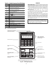
The machine operator communicates with the micro-
processor through the HSIO keypad anddisplay module. Com-
munication between the PSIO and the other modules is
accomplished by a 3-wire sensor bus. These 3 wires run in
parallel from module to module.
On the sensor bus terminal strips, terminal 1 of the PSIO1
module is connected to Terminal 1 of all of the other mod-
ules. Terminals 2 and 3 are connected in the same manner.
If any of the wires are crossed, the system will not work.
The unit processor modules, the high-voltage relay mod-
ules, and the HSIO keypad module are all powered from two
21-vac power sources which connect to terminals 1 and 2 of
the power input strip on each module.
53