


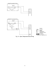
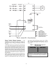
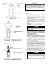


Gas Piping (48 Series Units Only) — Unit is equipped
for use with natural gas only. Installation must conform with
local building codes, or in the absence of local codes, with
the National Fuel Gas Code, ANSI Z223.1.
A
1
⁄
8
-in. NPT tapping plug, accessible for test gage con-
nection, must be field installed immediately upstream of gas
supply connection to unit, but after manual gas valve. See
Fig. 34. Natural gas pressure at unit gas connection must not
be less than 5 in. wg or greater than 13 in. wg.
Size gas supply piping for 0.5 in. wg maximum pressure
drop. Do not use supply pipe smaller than unit gas
connection.
Disconnect gas piping from unit when leak testing at
pressures greater than 0.5 psig. Pressures greater than
0.5 psig will cause gas valve damage resulting in a haz-
ardous condition. If gas valve is subjected to pressure
greater than 0.5 psig, it must be replaced.
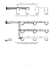
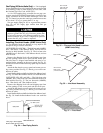
Installing Flue/Inlet Hoods (48MP Units Only)
—
The flue/inlet hoods are shipped in a bag taped to the
basepan in the gas section of the unit.
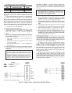
UNITS SIZES 62LAND 70M —The high heat units(48MPE),
have 3 flue hoods, 3 flue deflector hoods, and one inlet air
hood to be field installed. See Fig. 35. The low heat units
(48MPD) have 2 flue hoods, 2 flue deflector hoods, and one
inlet air hood.
Remove the shipping block offs and shipping tape from
the flue openings in the access panel and the corner post.
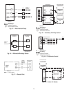
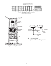
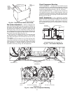
The inlet hood is shipped unassembled and must be as-
sembled before mounting to the access panel. See Fig. 36.
Install inlet screen on inlet hood using speed clips and screws
provided.
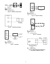
Attach the flue hoods to access panel and corner post us-
ing screws provided. See Fig. 37. Hoods go over each com-
bustion air outlet.
Install the flue deflector baffle inside the flue deflector hood.
See Fig. 38. Install flue deflector hoods over each flue hood.
UNIT SIZES 82N, 90P, and 10R — The high heat units
(48MPE), have 3 flue hoods and 3 flue deflector hoods to be
field installed. See Fig. 35. The low heat units (48MPD),
have 2 flue hoods and 2 flue deflector hoods.
Remove the shipping block offs and shipping tape from
the flue openings in the access panel and the corner post.
Attach the flue hoods to access panel and corner post us-
ing screws provided. See Fig. 37. Hoods go over each com-
bustion air outlet.
Install the flue deflector baffle inside the flue deflector hood.
See Fig. 38. Install the flue deflector hoods over each flue
hood.
INLET HOOD
(62L AND 70M
SIZES ONLY)
GAS HEAT
SECTION
PANEL
FLUE HOOD
AND FLUE
DEFLECTOR
HOOD
HIGH HEAT
UNITS ONLY
Fig. 35 — Flue and Inlet Hood Locations
(48MP Units Only)
INLET HOOD
INLET HOOD
SIDE PLATE
(TYP EACH SIDE)
Fig. 36 — Inlet Hood Assembly
Fig. 37 — Flue Hood
*NPT plug is field supplied.
NOTE: Follow all local codes.
Fig. 34 — Gas Piping Details
26