


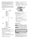
UNIT CONTROL BOX — Viewed facing compressors, the
control box is at the left end of the unit. Incoming power for
controls, refrigerant system, and fan system enters through
the control box. The control box contains power compo-
nents and electronic controls. Outer panels are hinged and
latched for easy opening. Remove screws to remove inner
panels. Outer panels can be held open for service and in-
spection by using a door retainer on each panel. Remove
bottom pin from door retainer assembly, swing retainer out
horizontally, and engage pin in one of the retainer ears in the
hinge assembly.
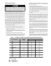
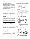
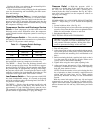
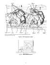
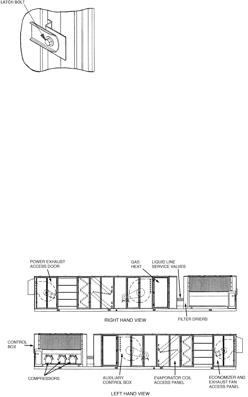
COMPRESSORS — The oil pump end (compressor access)
of each compressor is readily accessible from sides of unit
as shown in Fig. 51. Access the motor end of the compressor
through the condenser end of the unit or by removing
compressor.
LIQUID SERVICE VALVES, SOLENOID VALVES, FIL-
TER DRIERS, AND SIGHT GLASSES — These compo-
nents are located in the inside corner of the condenser sec-
tion on the right-hand side of the unit. Filter driers are
replaceable-core type. See Fig. 51.
EVAPORATOR-FAN MOTORS, PULLEYS, AND BELTS
— Access to these components is through the 2 doors
labeled FAN SECTION on each side of the unit.
POWER EXHAUST MOTORS, PULLEYS, AND BELTS
— Access to these components is through the doors at the
return air end of the unit.
GAS HEAT SECTION — Access to the gas heat section is
through the door labeled ‘‘HEAT SECTION’’ on the right
hand side of the unit. All gas system components are in the
gas section. On 48MP62L and 70M units, additional access
to the gas components is through the access panels in the
unit corner post at the gas section. See Fig. 51.
UNIT CONTROLBOX —Accessto this component is through
the doors marked ELECTRICAL SECTION on the con-
denser end of the unit.
ECONOMIZER DAMPER MOTORS — The economizer
motors are located in the return air section. Access to the
motors is through the doors labelled FAN SECTION on the
each side of the unit.
RETURN-AIR FILTERS —Access to these filters is through
the door marked FILTER SECTION on the right side of the
unit.
CONDENSER FANS AND FAN MOTORS — Remove the
wire fan guard on top of the unit to gain access to the con-
denser fans and motors.
Cleaning — Inspect unit at the beginning of each heating
and cooling season and during each season as operating con-
ditions may require.
Clean condenser coil with a vacuum cleaner, fresh water,
compressed air, or a bristle brush (not wire). Coil cleaning
should be a part of the planned maintenance program. Clean
evaporator coil with a stiff bristle brush (not wire), vacuum
cleaner, or compressed air.
Check and clean condensate drain annually at the start of
the cooling season.
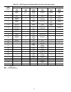
Replace return-air filters at the start of each heating and
cooling season or as often as necessary during each season,
depending on operating conditions. See Table 1 for filter types,
quantities, and sizes.
1. Remove economizer outdoor-air filters from the hoods by
removing the filter retainers.
2. Clean filters with steam or hot water and mild detergent.
3. Reinstall filters in hoods aftercleaning. Never replace clean-
able filters with throwaway filters.
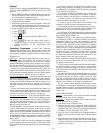
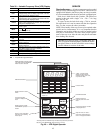
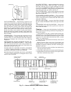
Fig. 50 — Door Latch
Fig. 51 — Access Locations (48MP70M Unit Shown)
46