


Replace the filter cores whenever the moisture/liquid in-
dicator shows moisture in the system.
Follow instructions on the packaging for the replacement
cores for disassembling and reassembling the filter assem-
blies and housings.
Liquid Line Service Valve — Located immediately
ahead of the filter drier, this valve has a
1
⁄
4
-in. flare connec-
tion for field charging. With the liquid circuit shut, the com-
pressor can be used to pump the refrigerant down into the
high side. The refrigerant can then be stored there by closing
the compressor discharge valve.
Compressor Suction and Discharge Service
Valves —
Each compressor is provided with suction and
discharge service valves. With these valves, the compressor
can be isolated from the refrigerant system for servicing or
replacing.
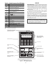
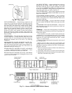
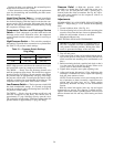
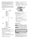
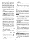
High-Pressure Switch — This switch has nonadjust-
able settings. Figure 60 shows connection on a cylinder head.
See Table 31 for pressure switch settings.
Table 31 — Pressure Switch Settings,
Psig (kPag)
SWITCH CUTOUT CUT-IN
High
426±7 320±20
(2935 ± 48) (2205 ± 138)
Low
27±4 67±7
(186 ± 28) (462 ± 48)
NOTE: High-pressure switch must be removed from cylin-
der head before removing compressor from the unit.
TO CHECK — Slowly close the discharge shutoff valve
until the compressor shuts down. This should be at approx-
imately 426 psig (2935 kPag). Slowly open the valve. When
the pressure drops to approximately 320 psig (2205 kPag),
the pressure switch resets. To reenergize the control circuit,
manually switch the fan circuit breaker off and then on. The
compressor starts again under Time Guard controls.
Low-Pressure Switch — The low-pressure switch (LPS)
has fixed nonadjustable settings. It is located at the pump
end of the compressor above the bearing head. See Table 31
for pressure switch settings.
TO CHECK — Slowly close the suction cut-off valve and
allow the compressor to shut down. This should occur at
approximately 27 psig (186 kPag). Slowly open the valve.
The compressor restarts under Time Guard control when the
pressure builds to approximately 67 psig (462 kPag).
Pressure Relief — High-side pressure relief is
provided by a fusible plug in the liquid line at the serv-
ice valve. For low-side pressure relief, a fusible plug is
inserted in the side of the accumulator. See Fig. 60. A pres-
sure relief valve installed on the compressor relieves at
450 psig (3102 kPag).
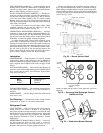
Adjustments
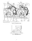
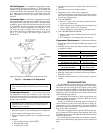
EVAPORATOR FAN AND POWER EXHAUST MOTOR
PLATE — Adjust using a
15
⁄
16
-in. wrench on the adjusting
bolts:
1. Loosen holddown bolts. (See Fig. 61.)
2. Turn the adjusting bolts to move the motor mounting plate
toward or away from the fan to loosen or tighten the belts.
Make the same number of turns to each bolt.
3. Retighten holddown bolts.
BELT INSTALLATION AND TENSIONING
IMPORTANT: When installing or replacing belts, al-
ways use a complete set of new, matched belts to pre-
vent potential vibration problems. Mixing belts often
results in premature breakage of the new belts.
1. Turn off unit power.
2. Adjust motor plate so belts can be installed without stretch-
ing over the grooves of the pulley. (Forcing the belts can
result in uneven belt stretching and a mismatched set of
belts.)
3. Before tensioning the belts, equalize belt slack so that it
is on the same side of the belt for all belts. Failure to do
so may result in uneven belt stretching.
4. Tighten belts using the motor plate adjusting bolts.
5. Adjust until proper belt tension (1/2-in. deflection with
one finger) is obtained. Be sure to adjust both adjusting
bolts the same number of turns.
NOTE: Check the tension at least twice during the first
day of operation, as there is normally a rapid decrease in
tension until the belts have run in. Check tension
periodically thereafter and keep it at the recommended
tension.
With the correct belt tension, belts may slip and squeal
momentarily on start-up. This slippage is normal and dis-
appears after wheel reaches operating speed. Excessive belt
tension shortens belt life and may cause bearing and shaft
damage.
50