


5. As actual SAT approaches CCSR value, stages are re-
leased. The minimum time delay between stages on de-
creasing demand is 90 seconds.
NOTE: Demand for heating has priority and Master Loop
will either terminate existing or prevent initiation of
Cooling Cycle by issuing a CCSR at the maximum limit.
This will cause the CSL to select zero stages of cooling
capacity, initiating a stoppage of an existing cooling cycle.
CV Units — Supply fan must be ON for cooling control to
operate. Sequence is as follows:
1. Master Loop will survey space temperature and space tem-
perature offset inputs, then calculate CCSR value.
2. The CSL surveys actual SAT, then calculates number of
capacity stages required to satisfy space load.
3. Stages of cooling capacity are initiated. (From zero stages,
there will be a 1.5 to 3 minute delay before first stage is
initiated.)
UNOCCUPIED COOLING — The unoccupied cooling
sequence of operation is similar to Occupied Cooling (see
above) except for the following:
1. Supply Fan will be OFF as demand is initiated.
2. The Master Loop will start Supply Fan and cooling cycle.
Fan status must be proved as ON within 2 minutes to con-
tinue with cooling operation.
3. Control set point will be Unoccupied Cooling Set Point
(UCSP).
4. At end of cooling cycle, Supply Fan will be turned OFF.
OVERRIDES
First Stage and Slow Change Override — The first stage over-
ride reduces cycling on the first stage of capacity, and the
slow change override prevents the addition or subtraction of
another stage of capacity if the SAT is close to the set point
and gradually moving towards the set point.
Low Temperature Override —This override function pro-
tects against rapid load decreases by removing a stage every
30 seconds when required based on temperature and the tem-
perature rate of change.
High Temperature Override — This override function pro-
tects against rapid load increases by adding a stage once
every 60 seconds as required, based on temperature and tem-
perature rate of change.
ADAPTIVE OPTIMAL START — Optimal start is used
to heat up or cool down the space prior to occupancy. The
purpose is to have the space temperature approach and then
achieve the occupied set point by the time of occupancy. The
control utilizes outdoor-air temperature, space temperature,
occupied set point, and a ‘‘K’’ factor. The ‘‘K’’ factor is ex-
pressed in minutes per degree, and calculates a start time
offset, which is the time in minutes that the system shall be
started in advance of the occupied time. The control moni-
tors its results and adjusts the ‘‘K’’ factor to ensure that the
occupied set point is achieved at time of occupancy rather
than too early or too late.
ADAPTIVE OPTIMAL STOP (CV Applications Only) —
Optimal stop is used to allow space temperature to drift to
an expanded occupied set point during the last portion of an
occupied period. The control calculates a stop time offset,
(the time in minutes prior to the scheduled unoccupied time)
during which expanded heating and cooling set points can
be used. Adaptive optimal stop utilizes space temperature,
an expanded occupied set point, and a ‘‘K’’ factor to calcu-
late stop time offset. The amount (F) to expand the occupied
set point is user configurable. Like adaptive optimal start,
the control corrects itself for optimal operation by adjusting
the ‘‘K’’ factor as required.
GAS HEATING, OPERATION (48MP Units Only) — Re-
fer to the Controls, Operation and Troubleshooting instruc-
tions for information on the control logic used by the unit
controls for gas heat operation.
The 48MPD units have 2 gas heat sections. The 48MPE
units have 3 gas heat sections. Each individual section op-
erates in the same manner.
NOTE: The 48MP units have 2 stages of heat.
When the PIC control calls for heating, power is sent to
W on each IGC (integrated gas controller) board. An LED
(light-emitting diode) on the IGC board will be on during
normal operation. A check is made to ensure that the rollout
switch and the limit switch are closed and the induced-draft
motor is not running. The induced-draft motor is then en-
ergized, and when speed is proven with the hall effect sensor
on the motor, the ignition activation period begins. The burn-
ers will ignite within 5 seconds.
If the burners do not light, there is a 22-second delay be-
fore another 5-second attempt. If the burners still do not light,
this sequence is repeated for 15 minutes. After the 15 min-
utes have elapsed, if the burners have not been lit, heating is
locked out. To reset the control, use the manual reset method
found in the Controls Operation and Troubleshooting book.
When ignition occurs the IGC board will continue to moni-
tor the condition of the rollout and limit switches, the hall
effect sensor, and the flame sensor.
When additional heat is required, W2 closes and initiates
power to the second stage of the main gas valve. When the
thermostat is satisfied, W1 and W2 open and the gas valve
closes, interrupitng the flow of gas to the main burners. If
the call for W1 lasted less than 1 minute, the heating cycle
will not terminate until 1 minute after W1 became active.
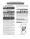
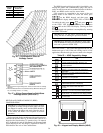
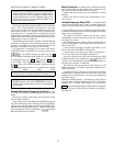
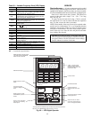
An LED indicator is provided on the IGC to monitor op-
eration. The IGC is located by removing the side panel and
viewing the IGC through the view port located in the control
box access panel. During normal operation, the LED is con-
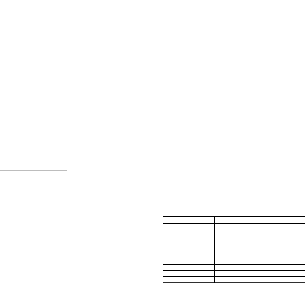
tinuously on. See Table 26 for error codes.
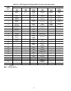
Table 26 — IGC Control Board LED Alarms
INDICATION ERROR MODE
ON Normal Operation
OFF Hardware Failure
1 FLASH Fan ON/OFF Delay Modified
2 FLASHES Limit Switch Fault
3 FLASHES Flame Sense Fault
4 FLASHES 4 Consecutive Limit Switch Faults
5 FLASHES Ignition Lockout Fault
6 FLASHES Induced Draft Motor Fault
7 FLASHES Rollout Switch Fault
8 FLASHES Internal Control Fault
LEGEND
IGC — Integrated Gas Unit Controller
LED — Light-Emitting diode
NOTES:
1. There is a 3-second pause between error code displays.
2. If more than one error code exists, all applicable error codes will
be displayed in numerical sequence.
3. Error codes on the IGC will be lost if power to the unit is
interrupted.
40