


Charging with Unit Off and Evacuated — Close liquid
line service valve before charging. Weigh in charge shown
in Table 1. Open liquid line service valve; start unit and
allow it to run several minutes fully loaded. Check for a clear
sight glass. Be sure clear condition is liquid and not vapor.
Complete charging the unit.
Charging with Unit Running — If charge is to be added while
unit is operating, it is necessary to have all condenser fans
and compressors operating. It may be necessary to block con-
denser coils at low-ambient temperatures to raise condens-
ing pressure to approximately 280 psig (1931 kPag) to turn
all condenser fans on. Do not totally block a coil to do this.
Partially block all coils in uniform pattern. Charge vapor into
compressor low-side service portlocated above oil pump crank-
shaft housing. Charge each circuit until sight glass shows
clear liquid.
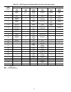
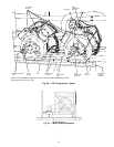
Oil Charge (Refer to Table 3) — All units are fac-
tory charged with oil.Acceptable oil level for each compres-
sor is from
3
⁄
8
to
1
⁄
8
(on 06E299,
1
⁄
8
max) of sight glass (see
Fig. 44, page 29).
When additional oil or a complete charge is required, use
only Carrier-approved compressor oil.
Approved oils are:
Petroleum Specialties, Inc. — Cryol 150A(factory oil charge)
Texaco, Inc. — Capella WF-32-150
Witco Chemical Co. — Suniso 3GS
Do not reuse drained oil, and do not use any oil that has
been exposed to atmosphere.
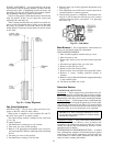
ADD OIL — Close suction shutoff valve and pump down
crankcase to 2 psig (14 kPa). (Low-pressure cutout must be
jumped.) Wait a few minutes and repeat until pressure re-
mains steady at 2 psig (14 kPa). Remove oil fill plug above
the oil level sight glass, add oil through plug hole, and re-
place plug. Run compressor for 20 minutes and check oil
level.
IMPORTANT: For units with 2 compressors per re-
frigeration circuit, both compressors must be running
to adjust the oil level. Two oil level equalizer lines be-
tween compressors distribute the oil to each
compressor.
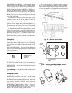
REMOVE OIL — Pump down compressor to 2 psig
(14 kPag). Loosen the
1
⁄
4
-in. (6.4-mm) pipe plug at the com-
pressor base and allow the oil to seep out past the threads of
the plug.
NOTE: The crankcase will be slightly pressurized. Do not
remove the plug, or the entire oil charge will be lost.
Small amounts of oil can be removed through the oil pump
discharge connection while the compressor is running.
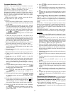
Moisture/Liquid Indicator — A clear flow of liquid
refrigerant indicates sufficient charge in the system. Bubbles
indicate undercharged system or the presence of non-
condensables. Moisture in the system measured in parts per
million (ppm) changes the color of the indicator:
Green — moisture below 45 ppm (dry)
Chartreuse — 45 to 130 ppm (caution!)
Yellow — moisture above 130 ppm (wet)
Change filter driers at the first sign of moisture in the sys-
tem. See Carrier Charging Handbook for more information.
IMPORTANT: Unit must be in operation at least
12 hours before moisture indicator can give an accu-
rate reading. With unit running, indicating element must
be in contact with liquid refrigerant to give a true
reading.
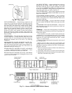
Filter Driers — The 48/50MP units use replaceable core
type filter driers, one in each refrigeration circuit. The filter
driers are located in the condenser sections, accessible from
the right side of the unit.
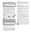
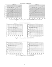
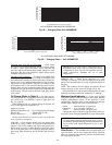
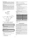
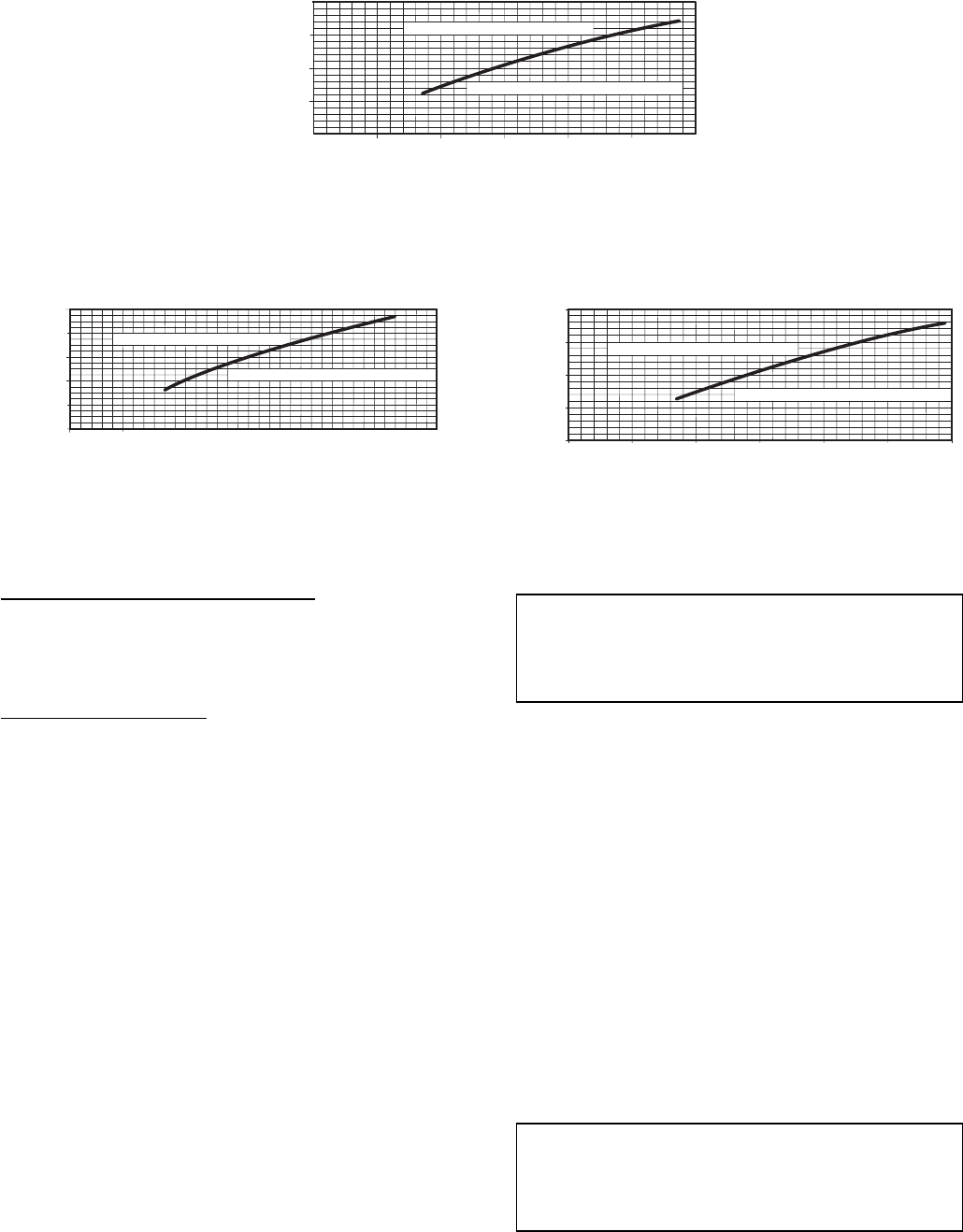
100 150 200 250 300 350 400
LIQUID PRESSURE AT LIQUID VALVE (PSIG)
REMOVE CHARGE IF BELOW CURVE
ADD CHARGE IF ABOVE CURVE
150
125
100
75
50
LIQUID TEMPERATURE
AT LIQUID VALVE (DEG F)
ALL OUTDOOR FANS MUST BE OPERATING
Fig. 58 — Charging Chart Unit 48/50MP90P
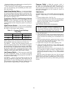
100
150
200
250
300
350
400 450
LIQUID PRESSURE AT LIQUID VALVE (PSIG)
REMOVE CHARGE IF BELOW CURVE
ADD CHARGE IF ABOVE CURVE
150
130
110
90
70
50
LIQIUD TEMPERATURE
AT LIQUID VALVE (DEG F)
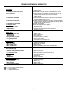
100 150 200 250 300 350 400
150
125
100
75
50
LIQUID PRESSURE AT LIQUID VALVE (PSIG)
LIQUID TEMPERATURE
AT LIQUID VALVE (DEG F)
ADD CHARGE IF ABOVE CURVE
REMOVE CHARGE IF BELOW CURVE
ALL OUTDOOR FANS MUST BE RUNNING
Fig. 59 — Charging Chart — Unit 48/50MP10R
49