


8. Once the submaster loop is adjusted, remove all forced
values and proceed with verification and adjustment of
master loop.
9. To check the master loop:
Create a demand in the master loop. For example: Force
the actual space temperature to a value less than the heat-
ing set point or greater than the cooling set point.
10. Observe system (loop) response for 10 to 20 minutes to
verify stable control. After 10 minutes, if the output con-
tinues to swing from full open to full closed, lower the
MLG and observe again.
11. Do this until the loop operation is stable. After 10 min-
utes, if the loop does not seem to respond (little change
in submaster reference), increase the MLG and observe
again. Do this until stable operation is achieved.
12. Once satisfied with loop operation, remove all forced
values which may have been initiated during this
procedure.
13. Repeat Steps 1-12 until all loops have been checked.
NOTE: For better tuning, the building supervisor or service
tool should be used to adjust the proportional and integral
terms. Contact your Carrier representative for more details.
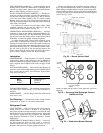
IAQ Control Loop Adjustment — The IAQ (indoor
air quality) control loop is different from the other control
loops. It has one gain value that can be adjusted in the serv-
ice subfunction ( ) under IAQG (indoor-air quality
gain). This gain is used to speed up or slow down the
response of the economizer dampers to the difference be-
tween the IAQ set point and the IAQ sensor. If the econo-
mizer is moving too slowly, then the gain needs to be
increased. If the economizer moves too rapidly and over-
shoots the set point, then the gain should be reduced.
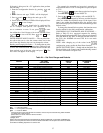
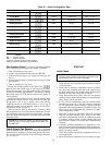
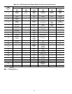
Lead/Lag Circuits — Lead/lag circuits and compres-
sors are shown in Table 20.
Table 29 — Index of Lead/Lag Circuits and
Compressors
UNIT 48/50MP 62L 70M 82N, 90P, 10R
LEAD CIRCUIT AA A
Compressor, Lead A1 A1 A1
Compressor, Lag *A2 A2
LAG CIRCUIT BB B
Compressor, Lead B1 B1 B1
Compressor, Lag ** B2
*Circuit only has 1 compressor.
Final Checks — Ensure all safety controls are opera-
ting, control panel covers are on, and the service panels are
in place.
Recheck all set points against project specifications. Com-
plete Start-Up Checklist and record operating values. Leave
completed checklist with unit for future reference.
NOTE: If the REMOTE START function is used in this ap-
plication, set the LOCAL/REMOTE switch to REMOTE (On)
at the end of start-up.
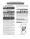
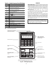
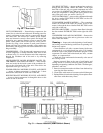
CONTROL SYSTEM
General —
The control system consists of the following
components:
• standard processor module (PSIO 8088 or PSIO1)
• options processor module (PSIO 8052 or PSIO2)
• two standard high-voltage relay modules (DSIO-HV or
DSIO1 and DSIO2)
• keypad and display module (HSIO or LID)
• enthalpy sensor
• thermistors
• pressure transducers
• accessory humidity sensors
• space temperature sensors (standard T55 andaccessory T56)
• supply-air fan status switch
• check filter switch
Components
PROCESSOR MODULE NO. 1 — The PSIO1 module moni-
tors and processes the following inputs, outputs, and system
information:
Inputs:
• transducers
• thermistors
• switches
Outputs:
• condenser-fan contactors
• integrated economizer motor (4 to 20 mA)
• optional supply duct static pressure control (VFD) (4 to
20 mA)
• optional modulating power exhaust control (VFD)
(4 to 20 mA)
System Information:
• generates alert and alarm information (via transducer, ther-
mistor, and sensor inputs)
• supports CCN level II communications
• supports digital air volume (DAV) interface
NOTE: The correct module address for the PSIO1 is 01 (S1
set at 0; S2 set at 1).
PROCESSOR MODULE NO. 2 — The PSIO2 module sup-
ports the sensors used for:
• humidity control
• outdoor-air cfm
• indoor-air quality (IAQ)
• smoke control
• superheat monitoring (only when accessory transducer ther-
mistor kit is field-installed).
In addition, the PSIO2 supplies the outputs for humidity
and hydronic heating coil control and a discrete output with
timed clock control (for outdoor building or parking lot lights).
NOTE: The correct module address for the PSIO2 is 31 (S1
set at 3; S2 set at 1).
HIGH-VOLTAGE RELAY MODULES (DSIO) —The DSIO
modules close contacts to energize evaporator and con-
denser fan contactors. The modules also control compressor
unloaders, compressor contactors, compressor crankcase heat-
ers, heat interlock function, and power exhaust contactor.
The compressor status through the compressor lockout (CLO)
relays and high-pressure switches (safety circuits) are the in-
puts to these modules.
NOTE: Thecorrect module addresses forthe DSIO1 and DSIO2
modules are 19 and 49, respectively. Set the switch closest
to the mounting plate at 1 (DSIO1) or 4 (DSIO2), and the
other switch at 9 (both modules).
42