


Page 13.2
13
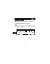
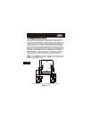
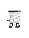
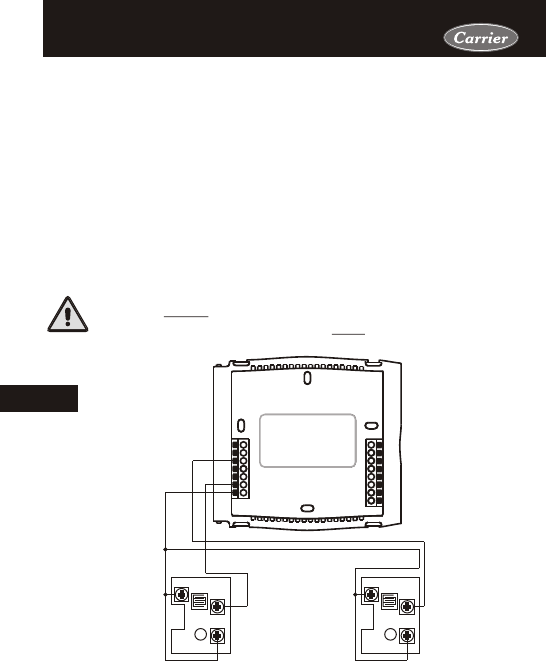
Installing the Remote SensorsInstalling the Remote Sensors
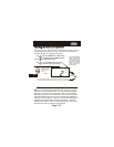
See the Remote Sensor accessory for further details.
RS-GND
RS
RS-GND
RS
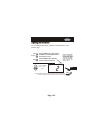
RS1 RS2
Y1
G
R
C
MISC2
CK1
CKGND
W1/O/B
MISC1
RS+5
RS1
RSGND
W2
Rs2
MISC3
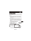
This wire MUST be completely separated from the thermostat or
any other control wiring and must NOT be in the same conduit
as high voltage wiring.
One wired or up to eight wireless
If
more than one wireless sensor is used on RS1, the thermostat will ave-
rage the sensors to determine the displayed temperature reading.
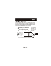
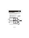
the degree icon on the thermostat will
blink once per second to indicate that a remote sensor reading is being
displayed. The wired sensor can be connected to the thermostat with
up to 150’ of 18 ga., 300’ of 20 ga., or 450’ of 22 ga. unshielded,
thermostat wire. The wired sensor can be connected to the therm-
ostat using a two or three wire installation. If a two wire installation is
required, then RS+5 must be connected to RSGND (see below).
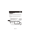
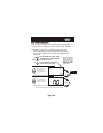
remote sensors may be installed on
the thermostat (RS1) to control the temperature in another room.
One
wired or wireless remote sensor may be installed to read the outside
temperature (RS2). If a sensor is connected to RS1 and is program-
med to control the thermostat,
RSRS