


Page 8.2
8
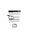
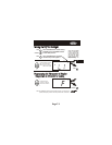
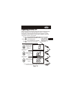
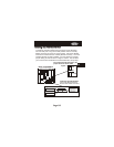
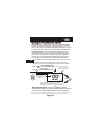
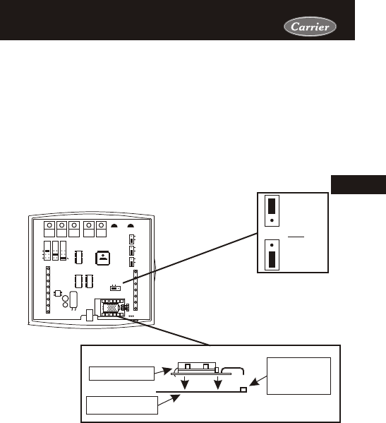
Figure 2
Installing the Humidity ModuleInstalling the Humidity Module
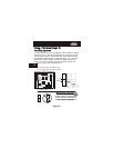
Back of 33CS400-01
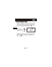
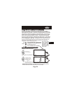
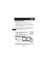
For proper humidity operation, this
jumper must be set for HUM.
HUM
NO HUM
OR
To install the Humidity Module the thermostat must be detached
from the back plate. Plug the Humidity Module into the Humidity
Module connector as shown in Figure 2 below. Follow the detailed
instructions included with the Humidity Module accessory. Once the
Humidity Module has been installed, you must adjust the Humidity
jumper setting to HUM as shown in Figure 1 below. This will allow
you to access the humidification and dehumidification setup steps.
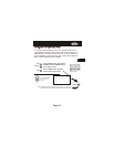
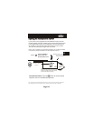
Humidity Module
Thermostat Circuit
Board.
Humidity Module
Plug located on
the Thermostat
Circuit Board.
Install the Humidity Module
(see Humidity Module Instruction
Sheet for more detailed information).
Figure 1
HP
GAS
B
O
ELEC
GAS
(FAN)
W1
Y1
G
R
C
MISC2
W2
MISC1
RS2
RSGND
MISC3
RS+5
Rs1
HUM
DEHUM
MISC3MISC2MISC1
Y2
(MISC1
ONLY)
INSTALL HUMIDITY
MODULE WITH SENSING
ELEMENT OUTWARD
HUM
NO HUM
1
2
4
6
8
X
Z
1
5
7
9
Y
3
CK1
CKGND
ECON