


6
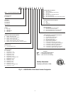
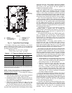
MOUNTING UNIT — When unit is in proper location, use
of mounting holes in base rails is recommended for securing
unit to supporting structure, or for mounting unit on vibration
isolators if required. See Fig. 4. Fasteners for mounting unit are
field supplied. Be sure unit is level to within
1
/
8
in. per foot for
proper oil return to compressor.
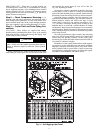
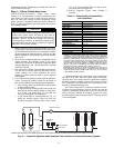
Step 2 — Check Compressor Mounting — As
shipped, units with single compressors are held down with 4
bolts through rubber grommets. All units with tandem com-
presors are held down with 6 bolts per pair through grommets.
After unit is installed, verify mounting bolt torque 7 to10 ft-lb.
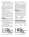
Step 3 — Cooler Fluid and Drain Piping Con-
nections
ALL UNITS — These chillers are supplied with factory-
installed strainer (including blow-down valve) in the entering
fluid piping and flow switch in the leaving fluid piping. Flow
switch wiring is factory installed. .
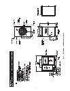
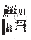
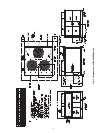
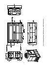
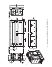
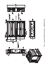
Piping connections are located on the front of the chiller
when facing the control panel for sizes 010 to 030 and at the
end opposite the control panel for sizes 035 to 060. See
Fig. 5-10, depending on model.
All sizes have victaulic connections as shown in the physi-
cal data tables. Provide a means of venting air from the high
point of the field-installed piping as required. Install field-sup-
plied drains in both the entering and leaving fluid connections.
After field piping is complete, freeze-up protection is rec-
ommended using inhibited ethylene glycol or other suitable in-
hibited antifreeze solution and electric heat tapes in areas
where piping is exposed to low ambient temperatures (34 F
[1 °C] or below). Heat tapes should possess a rating for area
ambients and be covered with a suitable thickness of closed-
cell insulation. Route power for heating tapes from a separately
fused disconnect. Identify disconnect as heat tape power source
with a warning that power must not be turned off except when
unit is being serviced.
The water connections are copper victaulic. Any connecting
pipe to the 30RAP pump package must be of a material that
will not cause any galvanic corrosion. For this reason, galva-
nized steel pipe or other dissimilar metals must not be used un-
less joined by a dielectric coupling.
Installation of water systems should follow sound engineer-
ing practice as well as applicable local and industry standards.
Improperly designed or installed systems may cause unsatis-
factory operation and/or system failure. Consult a water treat-
ment specialist or appropriate literature for information regard-
ing filtration, water treatment, and control devices.
CAUTION
Do not circulate water through unit without strainer in
place. Failure to use the strainer represents abuse and may
impair or otherwise negatively affect the Carrier product
warranty.
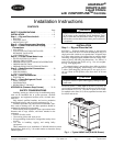
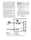
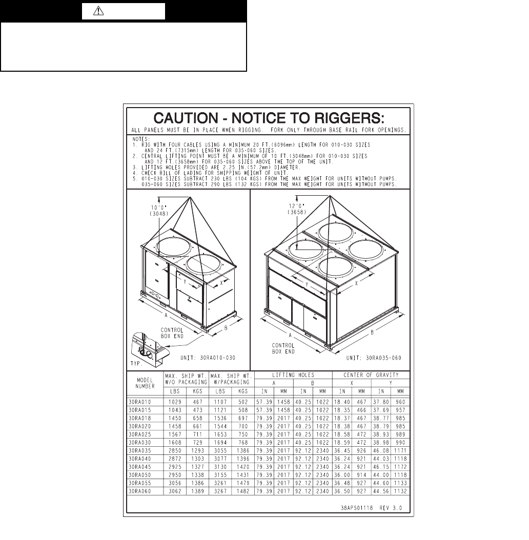
Fig. 4 — Unit Rigging Label Detail
a30-4916