


15
maintenance purposes, and that they be located where they can
be prevented from freezing.
Step 4 — Fill the Chilled Water Loop
WATER SYSTEM CLEANING — Proper water system
cleaning is of vital importance. Excessive particulates in the
water system can cause excessive pump seal wear, reduce or
stop flow, and cause damage of other components. Water
quality should be maintained within the limits indicated in
Table 3. Failure to maintain proper water quality may result in
heat exchanger failure.
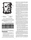
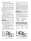
1. Install a temporary bypass around the chiller to avoid cir-
culating dirty water and particulates into the pump pack-
age and chiller during the flush. Use a temporary circulat-
ing pump during the cleaning process. Also, be sure that
there is capability to fully drain the system after cleaning.
(See Fig 14.)
2. Be sure to use a cleaning agent that is compatible with all
system materials. Be especially careful if the system
contains any galvanized or aluminum components. Both
detergent-dispersant and alkaline-dispersant cleaning
agents are available.
3. It is a good idea to fill the system through a water meter.
This provides a reference point for the future for loop
volume readings, but it also establishes the correct
quantity of cleaner needed in order to get the required
concentration.
4. Use a feeder/transfer pump to mix the solution and fill the
system. Circulate the cleaning system for the length of
time recommended by the cleaning agent manufacturer.
a. After cleaning, drain the cleaning fluid and flush the
system with fresh water.
b. A slight amount of cleaning residue in the system can
help keep the desired, slightly alkaline, water pH of 8
to 9. Avoid a pH greater than 10, since this will
adversely affect pump seal components.
c. A side stream filter is recommended (see Fig. 15)
during the cleaning process. Filter side flow rate
should be enough to filter the entire water volume
every 3 to 4 hours. Change filters as often as neces-
sary during the cleaning process.
d. Remove temporary bypass when cleaning is
complete.
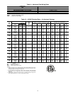
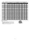
Table 3 — Water Quality Characteristics
and Limitations
*Sulfides in the water quickly oxidize when exposed to air, requiring that
no agitation occur as the sample is taken. Unless tested immediately
at the site, the sample will require stabilization with a few drops of one
Molar zinc acetate solution, allowing accurate sulfide determination up
to 24 hours after sampling. A low pH and high alkalinity cause system
problems, even when both values are within the ranges shown. The
term pH refers to the acidity, basicity, or neutrality of the water supply.
Below 7.0, the water is considered to b e acidic. Above 7.0, water is
considered to be basic. Neutral water contains a pH of 7.0.
†Dissolved carbon dioxide can either be calculated from the pH and
total alkalinity values, shown below, or measured on the site using a
test kit. Dissolved Carbon Dioxide, PPM = TA x 2
[(6.3-pH)/0.3]
where TA
= Total Alkalinity, PPM as CaCO
3
.
A 40-mesh strainer with a blow-down valve is standard on
all 30RAP units, both with and without hydronic packages.
The blow-down valve allows removal of particulates caught in
the strainer without complete removal of the screen. A female
NPT connection is provided on the valve, allowing hose con-
nection for drainage outside the unit.
The Carrier ComfortLink™ controls provided have a built-
in feature to remind building owners or operators to clean the
strainer by discharging the blow-down valve at a pre-set time
interval. Properly installed and cleaned systems will rarely
need the strainer cleaned after the initial fill. This time interval
is user-configurable.
CAUTION
Failure to properly clean all piping and components of the
chilled water system before unit start-up may result in
plugging of the heat exchanger, which can lead to poor per-
formance, nuisance alarms and damage from freezing.
Freezing damage caused by an improperly cleaned system
represents abuse and may impair or otherwise negatively
affect the Carrier product warranty.
WATER CHARACTERISTIC QUALITY LIMITATION
Alkalinity (HCO
3
-
) 70 – 300 ppm
Sulfate (SO
4
2-
) Less than 70 ppm
HCO
3
-
/SO
4
2-
Greater than 1.0
Electrical Conductivity 10 – 500S/cm
pH 7.5 – 9.0
Ammonium (NH
3
) Less than 2 ppm
Chorides (Cl
-
) Less than 300 ppm
Free chlorine (Cl
2
) Less than 1 ppm
Hydrogen Sulfide (H
2
S)* Less than 0.05 ppm
Free (aggressive) Carbon
Dioxide (CO
2
)†
Less than 5 ppm
Total Hardness (dH) 4.0 – 8.5
Nitrate (NO
3
) Less than 100 ppm
Iron (Fe) Less than 0.2 ppm
Aluminum (Al) Less than 0.2 ppm
Manganese (Mn) Less than 0.1 ppm
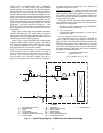
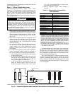
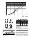
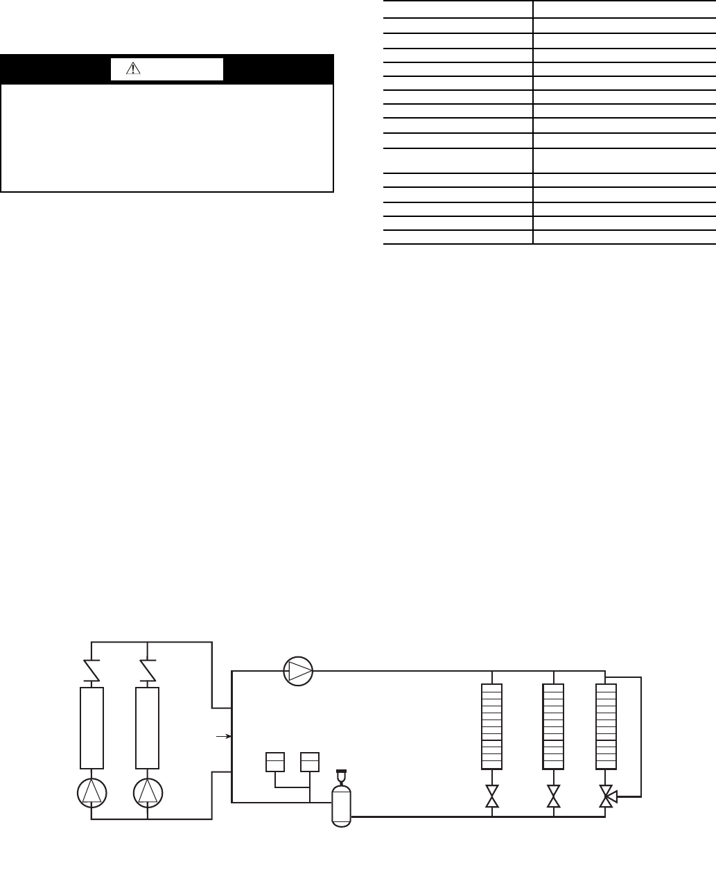
Distribution Pump
Expansion
Tank(s)
Air Separator
with Vent
Decoupler
Chiller 1
Chiller 2
Zone 1
Zone 2
Zone 3
NOTE: Expansion tanks in the 30RAP hydronic kits must be disconnected for chillers placed parallel in the primary water loop.
Fig. 13 — Typical Air Separator and Expansion Tank Location on Primary-Secondary Systems