29
POWER WIRING — All power wiring must comply with
applicable local and national codes. Install field-supplied
branch circuit fused disconnect per NEC (National Electric
Code, U.S.A.) of a type can be locked OFF or ON. Disconnect
must be within sight from and readily accessible from unit in
compliance with NEC Article 440-14.
General Wiring Notes
1. The control circuit does NOT require a separate power
source. Control circuit power is obtained by a step-down
transformer from the main three-phase power supply. The
LVT (low voltage terminal) strip is provided for field-
wired control devices.
2. Cooler and pump heaters (if factory installed) are wired
in the control circuit so they are operable as long as the
main power supply to the unit is ON. A factory-installed
and set overload device protects them.
NOTE: The field-supplied disconnect should never be off
except when unit is being serviced or is to be down for a pro-
longed period, in which case cooler should be drained.
3. Power entry is at the right-hand side of the unit when fac-
ing the control box.
4. Maximum field wire sizes allowed by lugs on terminal
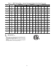
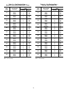
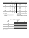
block/non-fused disconnect are listed in Table 8.
5. Terminals for field power supply are suitable for
copper conductors. Insulation must be rated 167 F (75 C)
minimum.
FIELD CONNECTIONS
Main Power
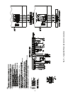
— Bring wires from the fused disconnect switch
through hole in the middle of the right hand corner post to the
bottom of the control box and connect to terminals on terminal
block or non-fused disconnect. A
7
/
8
-in. hole is provided in the
corner post to locate the center of the field power entry. To
comply with NEC Article 440-14, the disconnect must be lo-
cated within sight from and readily accessible from unit. Refer
to Fig. 19.
Control Power
— Control power is obtained from the main
power supply and does NOT require a separate source. A
toggle switch (marked Emergency On-Off on the unit label
diagram and by the switch) allows the control circuit to be
manually disconnected when necessary. Cooler and pump
heaters (if installed) are in an operable state when this switch is
in the Off position.
Step 6 — Install Accessories
ELECTRICAL — A number of electrical accessories are
available to provide the following optional features (for details,
refer to the Controls, Start-Up, Operation, Service, and
Troubleshooting book):
Energy Management Module
(Used for any of the following
types of temperature reset, demand limit and ice features):
• 4 to 20 mA leaving fluid temperature reset (requires
field-supplied 4 to 20 mA generator)
• 4 to 20 mA cooling set point reset (requires field-
supplied 4 to 20 mA generator)
• Discrete inputs for 2-step demand limit (requires field-
supplied dry contacts)
• 4 to 20 mA demand limit (requires field-supplied 4 to
20 mA generator)
• Discrete input for Ice Done switch (requires field-
supplied dry contacts)
Navigator™ Display
— The device provides hand-held,
mobile capability using an easy to read 4-line display. The key-
pad function is the same as the scrolling marquee module. A
magnet is provided for ‘hands free’ service of components.
Low Ambient Operation
— If outdoor ambient operating
temperatures below 45 F (7 C) on size 018-030 units or 32 F
(0° C) on size 035-060 units are expected, refer to separate in-
stallation instructions for low-ambient operation using accesso-
ry Motormaster
®
V control. Size 010 and 015 units have Mo-
tormaster V installed as standard.
Minimum Load Accessory
— If minimum load accessory is
required, refer to unit Price Pages or contact your local Carrier
representative for more details. For installation details, refer to
separate installation instructions supplied with the accessory
package.
Miscellaneous Accessories
— For applications requiring spe-
cial accessories, the following packages are available: external
vibration, remote enhanced display, temperature reset, con-
denser coil covers, storage tank, wind baffles, and remote cool-
er. For installation details, refer to separate installation instruc-
tions supplied with these accessory packages.
Step 7 — Check Refrigerant Circuit
LEAK TESTING — Units are shipped with complete operat-
ing charge of R-410A (refer to physical data tables) and should
be under sufficient pressure to conduct a leak test. Perform a
leak test to ensure that leaks have not developed during unit
shipment. Dehydration of the system is not required unless the
entire refrigerant charge has been lost. Repair any leak found
using good refrigeration practice.
DEHYDRATION — Refer to Carrier Standard Service Tech-
niques Manual, Chapter 1, Refrigerants, Sections 6 and 7 for
details. Do not use compressor to evacuate system.
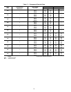
REFRIGERANT CHARGE (Refer to Tables 1A and
1B) — Immediately after the condenser coil in each circuit is a
1
/
4
-in. Schrader connection for charging liquid refrigerant.
Utilization of Novation condenser coil technology enables
the 30RAP chiller to have a very low refrigerant charge. There-
fore, if field charging is required, accurately charging to the
correct quantity is very important. It is necessary to ensure that
the system is completely evacuated before charging and that
the refrigerant charge is accurately weighed to within 1% of the
nameplate quantity or the unit may not operate correctly.
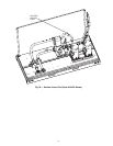
The suction lines are provided with a
1
/
4
-in. Schrader fitting
for connecting to low-side system pressure. The location of the
suction access port is shown in Fig. 20.
IMPORTANT: To ensure power to the heaters, make sure
auxiliary power to the unit and the compressor circuit
breakers is always on (except for servicing or prolonged
shutdown).
CAUTION
Proper rotation of condenser fan(s) MUST be verified
before pumps or compressors are started. Consult the Con-
trols, Start-Up and Operation manual provided with this
chiller for correct procedure. Improper pump rotation can
cause permanent damage to pump impeller and housing. If
pump(s) have been removed for trimming, verify that wir-
ing is reconnected in the original manner.
CAUTION
When charging, circulate water through the cooler at all
times to prevent freezing. Freezing damage is considered
abuse and may impair or otherwise negatively affect the
Carrier warranty.
CAUTION
DO NOT OVERCHARGE system. Overcharging results
in higher discharge pressure, increased power consump-
tion, and possible compressor damage.


