


Manufacturer reserves the right to discontinue, or change at any time, specifications or designs without notice and without incurring obligations.
Catalog No. 04-53300036-01 Printed in U.S.A. Form 30RAP-1SI Pg 1 11-09 Replaces: New
Installation Instructions
CONTENTS
Page
SAFETY CONSIDERATIONS. . . . . . . . . . . . . . . . . . . . . . 1
INSTALLATION . . . . . . . . . . . . . . . . . . . . . . . . . . . . . . . . 1-31
Step 1 — Rig and Place the Unit. . . . . . . . . . . . . . . . . . 1
•RIGGING
•PLACING UNIT
• MOUNTING UNIT
Step 2 — Check Compressor Mounting . . . . . . . . . . 6
Step 3 — Cooler Fluid and Drain Piping
Connections . . . . . . . . . . . . . . . . . . . . . . . . . . . . . . . . . . . 6
• ALL UNITS
• UNITS WITH FACTORY-INSTALLED
HYDRONIC PACKAGES
•AIR SEPARATION
Step 4 — Fill the Chilled Water Loop . . . . . . . . . . . . 15
• WATER SYSTEM CLEANING
• FILLING THE SYSTEM
• PREPARATION FOR YEAR-ROUND OPERATION
• FREEZE PROTECTION
• PREPARATION FOR WINTER SHUTDOWN
Step 5 — Make Electrical Connections . . . . . . . . . . 20
• POWER SUPPLY
•POWER WIRING
• FIELD CONNECTIONS
Step 6 — Install Accessories . . . . . . . . . . . . . . . . . . . . 29
• ELECTRICAL
Step 7 — Check Refrigerant Circuit . . . . . . . . . . . . . 29
• LEAK TESTING
• DEHYDRATION
• REFRIGERANT CHARGE
APPENDIX A (Pressure Drop Curves) . . . . . . . . 32-38
SAFETY CONSIDERATIONS
Installing, starting up, and servicing air-conditioning equip-
ment can be hazardous due to system pressures, electrical
components, and equipment location (roofs, elevated struc-
tures, etc.).
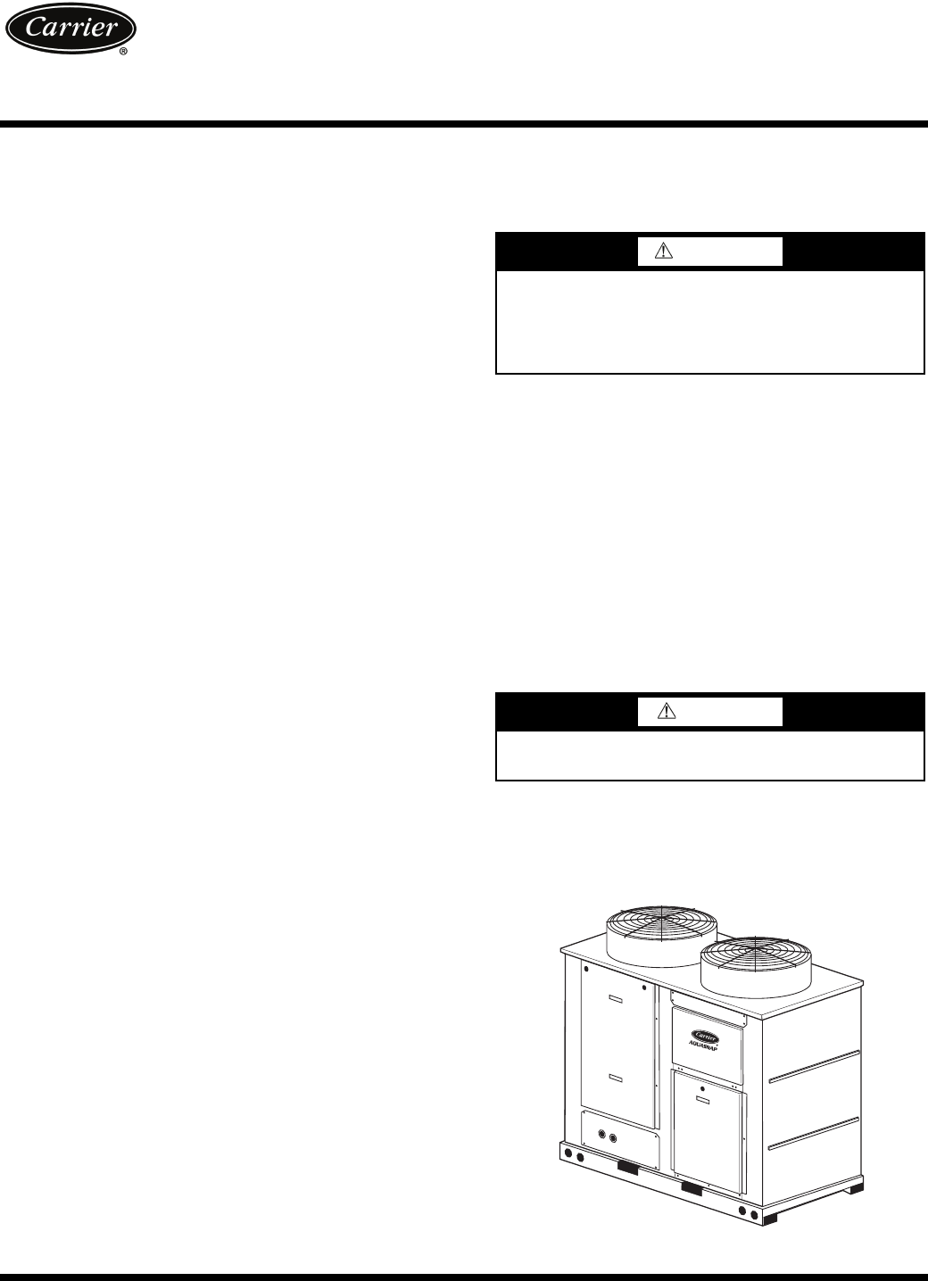
Only trained, qualified installers and service mechanics
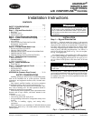
should install, start up, and service this equipment (Fig. 1).
Untrained personnel can perform basic maintenance func-
tions such as cleaning coils. All other operations should be
performed by trained service personnel.
When working on the equipment, observe precautions in the
literature and on tags, stickers, and labels attached to the
equipment.
• Follow all safety codes.
• Wear safety glasses and work gloves.
• Keep quenching cloth and fire extinguisher nearby when
brazing.
• Use care in handling, rigging, and setting bulky
equipment.
.
INSTALLATION
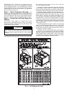
Step 1 — Rig and Place the Unit
RIGGING — Preferred method for rigging is with spreader
bars from above the unit. Use hooks in lifting holes. Rig at a
single point with 4 cables or use spreader bars. All panels must
be in place when rigging. See rigging label on unit for details
concerning shipping weights, distance between lifting holes,
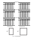
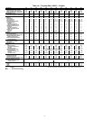
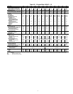
center of gravity, and lifting ring dimensions. See Tables 1A
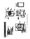
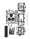
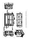
and 1B for physical data. Refer to Fig. 3 for unit weights.
See Fig. 4 for rigging label.
If overhead rigging is not possible, place chiller on skid or
pad for rolling or dragging. When rolling, use a minimum of
3 rollers. When dragging, pull the pad. Do not apply force to
the unit. When in final position, raise from above to lift unit
off pad.
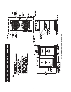
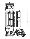
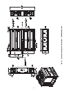
PLACING UNIT — There must be at least 3 ft (0.9 m) for
service and for unrestricted airflow on all non-coil sides of unit,
and a minimum of 3.5 ft (1.1 m) clear air space on coil sides.
For multiple units, allow 8 ft (2.48 m) separation between units
for airflow and service.
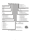
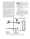
These instructions cover installation of 30RAP010-060 air-cooled
liquid chillers. Refer to Fig. 2 for model number to determine factory-
installed options.
WARNING
Electrical shock can cause personal injury and death. Shut
off all power to this equipment during installation. There
may be more than one disconnect switch. Tag all discon-
nect locations to alert others not to restore power until work
is completed.
CAUTION
All panels must be in place when rigging. Damage to unit
could result.
AQUASNAP
®
30RAP010-060
Liquid Chillers
with COMFORTLINK
TM
Controls
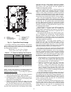
Fig. 1 — Typical 30RAP Unit (018-030 Shown)