


72
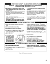
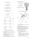
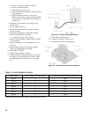
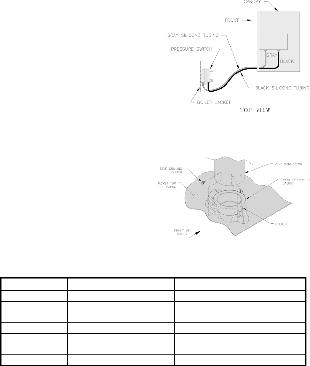
Figure 42: Silicone Tubing Assembly
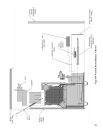
Figure 43: Blower Vent Connector Assembly
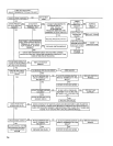
d. Remove wires to Flame Roll-out Switch.
e. Remove air diffuser screen.
f. Remove Burner Access Panel.
g. Mark location of Main Burner with Pilot Bracket
on gas manifold.
h. Hold Main Burner on throat. Lift front of
burners to clear orice. Burner which holds pilot
can be removed by lifting the burner adjacent to
its right rst.
2. Disconnect Vent Connector and Vent Pipe from
Blower Outlet
3. Remove Jacket Top Panel.
4. Disconnect the Black and Gary Silicone Tubing
from the Canopy.
5. Disconnect Wiring Harness from Blower Motor.
6. Remove Canopy/Blower Assembly.
a. Loosen the (4) screws from Canopy.
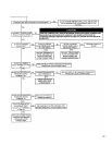
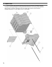
7. Remove Flue Gas Bafes. Inspect Flue Gas Bafes
for deterioration.
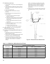
8. Inspect ue passages. Clean with ue brush. See
Figure 44.
9. Inspect heating surface in combustion chamber.
Clean with straight handle wire brush.
10. Install Flue Gas Bafes.
11. Replace Canopy/Blower Assembly.
12. Connect Silicone Tubing between Pressure Fittings
on Canopy Assembly and Pressure Switch. Route
through bushings in Vestibule Panel . See Figure
42.
13. Install Jacket Top Rear Panel.
14. Connect Vent System. See Figure 43.
15. Connect Blower Motor Wiring Harness.
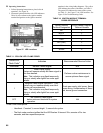
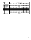
TABLE 14: PILOT BURNER LOCATION
Boiler Model Main Burner with Pilot Bracket Pilot Burner Located Between Main Burners *
SCG-3 2 2 & 3
SCG-4 3 3 & 4
SCG-5 4 4 & 5
SCG-6 5 5 & 6
SCG-7 6 6 & 7
SCG-8 7 7 & 8
SCG-9 8 8 & 9
* Main burners numbered left to right as viewed from front of boiler.