


17
Vertical Venting –
1. See Figure 43 on Page 72 for Blower Vent
Connector Assembly. Do not exceed maximum vent
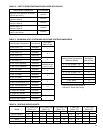
lengths. Refer to Table 4.
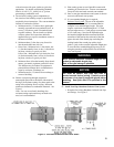
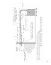
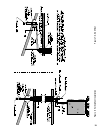
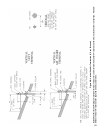
2. Installation of a vertical vent drain tee 8116304U
is required on all vertical vent applications. See
Figures 6 and 7. Attach vertical vent drain tee
directly to elbow or horizontal pipe from an elbow
immediately after vent connector.
3. Slope horizontal runs minimum ¼ inch per foot.
Slope towards vertical vent drain tee. Position weld
seams in vent pipes, in all horizontal runs, at the top
to avoid condensate from lying on the seams.
4. Install re stops where vent passes through oors,
ceilings or framed walls. The re stop must close
the opening between the vent pipe and the structure.
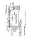
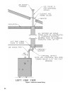
5. Whenever possible, install vent straight through
the roof. Refer to Figure 7 if offset is necessary.
Maintain minimum clearance to combustible
materials.
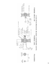
6. Install Vent Terminal.
a. Size roof opening to maintain minimum
clearance from combustible materials.
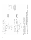
b. Extend vent pipe to maintain minimum vertical
and horizontal distance of twelve (12) inches
from roof surface. Allow additional vertical
distance for expected snow accumulation.
Provide brace as required. Refer to Figures 8A
and 8B.
NOTICE
Vertical venting requires the use of roof ashing
and a storm collar to prevent moisture from
entering the structure.
c. Install storm collar on vent pipe immediately
above ashing. Apply Dow Corning Silastic 732
RTV Sealant between vent pipe and storm collar
to provide weathertight seal.
d. Attach vent terminal.
Vertical Air Intake Piping –
7. Do not exceed maximum air intake length. Refer to
Table 4.
8. Locate air intake termination on the same roof
location as the vent termination if possible, to
prevent nuisance boiler shutdowns. However, boiler
may be installed with vertical venting and sidewall
combustion air inlet or visa versa, if installation
conditions do not allow alternate arrangement.
9. Use single wall metal pipe or PVC and ttings
available at most heating distributors.
a. Air intake pipe diameter is based on boiler size.
SCG-3 & SCG-4 uses 3 inch diameter piping.
SCG-5 & SCG-6 uses 4 inch diameter piping.
SCG-7 thru SCG-9 uses 5 inch diameter piping.
10. Air intake termination must be located:
Vertical - At least twelve (12) inches above the roof
surface plus the expected snow accumulation.
11. Start at collar on burner enclosure (inside boiler
jacket) and work towards the air intake terminal.
12. Maintain minimum of ¼ inch per foot slope on
horizontal runs. Slope down towards boiler.
13. The air intake pipe must be adequately supported
with straps or supports no less than ve (5) feet
apart on horizontal runs. The complete air intake
piping system must be rigid and able to withstand
minor impacts without collapse.
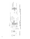
14. Inlet air pipe penetration:
Vertical - Size roof opening to allow easy insertion
of inlet piping and allow proper installation of
ashing and storm collar.
a. Use appropriately designed vent ashing
when passing through roofs. Follow ashing
manufacturers’ instructions for installation
procedures. Flashing manufacturers are Air-
Jet, American Metal Products, Metal Fab, and
Simpson Dura-Vent.
b. Extend air intake pipe to maintain minimum
vertical and horizontal distance of twelve
(12) inches from roof surface. Allow
additional vertical distance for expected snow
accumulation. Provide brace as required. Refer
to Figures 8A and 8B.
c. Vertical air intake requires ashing and a storm
collar to prevent moisture from entering the
structure.
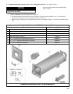
E. Separate Vertical Venting System - See Figures 6, 7, 8A, 8B and 9.
NOTICE
Roof penetrations require the use of roof ashing
and storm collar - not supplied with boiler.