


12
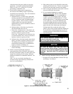
a. Wipe the male end of each joint using an alcohol
pad to remove any dirt and grease.
b. Align weld seams in pipes and use a slight
twisting motion to FULLY insert male end into
female end of joint. Ensure bead in male end
of pipe is below locking band and rest against
the end of the female pipe. Verify the factory-
installed gasket is not dislodged or cut.
c. Tighten locking band by HAND with a 5/16”
nut driver until snug plus ¼ turn. DO NOT
SECURE JOINTS WITH SHEET METAL
SCREWS OR POP RIVETS. DO NOT
PUNCTURE THE VENT SYSTEM!
d. Once the installation is complete, operate
appliance and inspect all joints to ensure that ue
gases and/or liquid condensate will not escape.
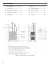
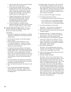
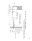
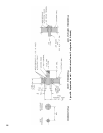
D. Separate Horizontal Venting System. See Figures
4A, 4B, 5A and 5B. See Figure 43 on Page 72 for
Blower Vent Connector Assembly.
Vent Piping –
1. This boiler is supplied with components as standard
equipment for installation of the separate horizontal
venting system.
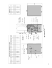
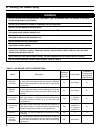
2. Do not exceed maximum vent/air intake lengths.
Refer to Table 4.
3. Recommended horizontal installation consists
of vent being sloped down ¼ inch per foot away
from boiler. See Figure 4A. See Figure 48 for an
alternate horizontal installation.
4. Use appropriate designed thimbles when passing
through combustible walls (thimble use optional for
noncombustible walls). Insert thimble through wall
from outside. Secure outside ange to wall with
nails or screws, and seal ID, OD and vent holes with
sealant material. Install inside ange to inside wall,
secure with nails or screws, and seal with sealant
material.
5. For noncombustible wall application when thimble
is not used, size opening such that bell with locking
band attached cannot pass through.
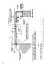
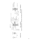
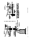
6. Join vent terminal to vent pipe. See Figures 5A and
5B.
7. Insert vent pipe through thimble/opening from
outside and join to vent system. Apply sealant
between vent pipe and opening/thimble to provide
weathertight seal.
Air Intake piping - See Figures 4A, 4B, 5A and 5B.
8. Locate air intake termination on the same wall as
the vent termination if possible, to prevent nuisance
boiler shutdowns. However, boiler may be installed
with vertical venting and sidewall combustion air
inlet or visa versa, if installation conditions do not
allow alternate arrangement.
9. Do not exceed air intake length. See Table 4.
10. Use single wall metal or PVC pipe.
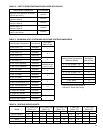
a. Air intake pipe diameter is based on boiler size.
SCG-3 & SCG-4 uses 3 inch diameter piping.
SCG-5 & SCG-6 uses 4 inch diameter piping.
SCG-7 thru SCG-9 uses 5 inch diameter piping.
11. Air intake termination must be located:
Horizontal - At least twelve (12) inches above
grade plus the expected snow accumulation.
12. Start at collar on boiler jacket and work towards the
air intake terminal.
13. Maintain minimum of ¼ inch per foot slope on
horizontal runs. Slope towards air inlet terminal
when possible. If not, slope towards boiler.
14. The air intake pipe must be adequately supported
with straps or supports no less than ve (5) feet
apart on horizontal runs. The complete air intake
piping system must be rigid and able to withstand
minor impacts without collapse.
15.
Inlet air pipe penetration:
Horizontal - Size wall penetration to allow easy
insertion of air inlet piping. Seal around pipe with
sealant to form weathertight exterior joint.
16. Seal all joints airtight, using silicone caulk or self-
adhesive aluminum tape.
17.
Install Air Intake Terminal:
Horizontal - Remove four (4) screws from cover
plate and remove cover plate from terminal. Insert
intake piping into intake terminal collar. Secure
terminal to intake piping and seal joint with silicone
caulk or self-adhesive aluminum tape. Apply
continuous bead of silicone caulk around the back
of the intake terminal, approximately ¼ inch from
its edge. Push inlet terminal inward until terminal’s
back ange is against the wall surface. Secure the
terminal with noncorrosive fasteners (stainless steel,
brass or aluminum) to the wall. Reinstall the cover
plate with four (4) screws. Apply a bead of silicone
caulk to perimeter of intake terminal’s back ange
to provide a weathertight seal.