


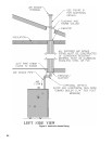

24
c. From exterior of building, insert air box sub-
assembly into square opening. Push air box
inward until wall ange is against wall, check
for level and mark the location of the four (4)
securing holes on the exterior wall. Remove air
box from wall.
d. Drill four (4) pilot holes, properly sized for the
non-corrosive fasteners (stainless steel, brass, or
aluminum) to be used to secure the wall ange to
the exterior wall. (Securing screws not supplied
with kit.)
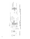
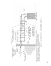
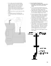
e. Attach four (4) 1/2 inch long threaded aluminum
spacers to the outer anges of the exterior
wall ange with four (4) number 10 - 32 x 1/4
inch stainless steel machine screws provided.
(See Figure 11.)
f. Apply a 1/4 inch thick continuous bead of
silicone caulk to perimeter of exterior wall
ange’s back surface to provide a weathertight
seal.
g. Reinstall air box sub-assembly into opening in
exterior wall and secure to wall.
WARNING
Non-corrosive fasteners must be used.
h. Apply a bead of silicone caulk to perimeter of
wall ange, where the wall and ange join. Use
a tool or your nger and apply pressure while
smoothing caulking to provide a weathertight
seal.
i. From interior of building, insert end panel with
collar and vent pipe assembly into open end of
air box sub-assembly. (See Figure 11.)
j. Secure end panel to air box sub-assembly with
shipping screw and thirteen (13) number 8 sheet
metal screws provided.
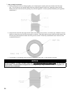
k. From exterior of building, position 10 inch
square exterior wall cover over exterior wall
ange. Insert 3 inch diameter vent pipe into
center opening in terminal cover. Align four
(4) holes on cover with 1/2 inch long threaded
spacers on wall ange. Secure terminal cover
with four (4) number 10 - 32 x 1/4 inch stainless
steel machine screws provided.
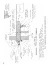
l. Apply a bead of silicone caulk to perimeter of
plate-seal and around pipe. Secure plate-seal to
exterior cover with six (6) #8 stainless steel sheet
metal screws provided. Smooth caulk around
plate-seal and pipe to provide weathertight seal.
m. Install Vent Terminal supplied with boiler to vent
pipe penetrating through terminal cover. Join
terminal and pipe with locking band and seal
with RTV (see Figure 3).
3.
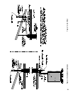
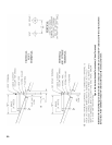
Install Vent Piping. See Figures 10 and 11.
a. Start at vent connector on boiler, see Figure 43
on Page 72, and work towards combination vent/
air terminal.
b. Installation of a vertical vent tee 8116304U is
required on all vertical vent applications. See
Figures 12 and 13. Attach vertical vent drain
tee directly to elbow or horizontal pipe from an
elbow immediately after vent connector.
c. Slope horizontal runs minimum ¼ inch per foot.
Slope towards vertical vent drain tee. Position
weld seams in vent pipes, in all horizontal runs,
at the top to avoid condensate from lying on the
seams.
d. Use 3/4 inch pipe strap to support horizontal runs
and maintain vent location and slope. Maximum
support spacing is ve (5) feet.
e. Install vent piping to connect vent connector
on boiler and combination vent/air terminal.
Reference Section B - General Venting
Guidelines for proper procedure for joining pipe
and ttings.
f. Connect vent piping to combination vent/air
terminal. See Figure 10.
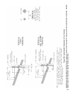
4.
Install Air Intake Piping. See Figures 10 and 11.
a. Do not exceed air intake length. See Table 4.
b. Use single wall metal pipe or PVC and ttings
available at most heating distributors.
c. Air intake pipe diameter is based on boiler size.
SCG-3 & SCG-4 uses 3 inch diameter piping.
SCG-5 & SCG-6 uses 4 inch diameter piping.
SCG-7 thru SCG-9 uses 5 inch diameter piping.
d. Start at collar on burner enclosure (inside boiler
jacket) and work towards the combination vent/
air terminal.
e. Maintain minimum of 1/4 inch per foot slope on
horizontal runs. Slope down towards boiler.
f. The air intake pipe must be adequately supported
with straps or supports no less than ve (5)
feet apart on horizontal runs. The complete air
intake piping system must be rigid and able to
withstand minor impacts without collapse.
g. Connect Air Intake Piping to Combination Vent/
Air Terminal. See Figure 10.
NOTE: When installing 3 inch diameter air intake
piping for a SCG-3 or SCG-4 application, the use of
a 4 inch x 3 inch reducer will be required to connect
air intake piping to combination vent/air terminal.
(Reducer included with combination horizontal
venting kit).
h. Seal all joints airtight, using silicone caulk or
self-adhesive aluminum tape.