


37
11. Install re stops where vent passes through oors,
ceilings or framed walls. The re stop must close
the opening between the vent pipe and the structure.
Fire stop manufacturers are Air-Jet, American Metal
Products, Metal-Fab, and Simpson Dura-Vent.
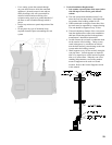
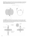
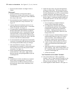
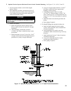
12. Whenever possible install vent straight through roof.
Refer to Figure 6. Maintain minimum clearance to
combustible materials. For attic offset see Figure 7.
13. Install Vent Terminal.
a. Size roof opening to maintain minimum
clearance from combustible materials.
b. Use appropriately designed vent ashing
when passing through roofs. Follow ashing
manufacturers’ instructions for installation
procedures. Flashing manufacturers are Air-
Jet, American Metal Products, Metal Fab, and
Simpson Dura-Vent.
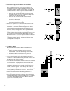
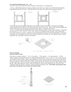
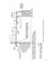
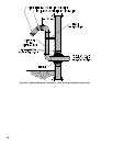
c. Extend vent pipe to maintain minimum vertical
and horizontal distance of twelve (12) inches
from roof surface. Allow additional vertical
distance for expected snow accumulation.
Provide brace as required. Refer to Figure 15.
d. Vertical venting requires ashing and a storm
collar to prevent moisture from entering the
structure.
e. Install storm collar on vent pipe immediately
above ashing. Apply Dow Corning Silastic 732
RTV Sealant between vent pipe and storm collar
to provide weathertight seal.
f. Attach vent terminal.
Vent Terminal and Air Intake Terminal –
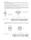
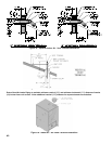
14. Join vent terminal to 45° elbow (supplied by
installer). Join 45° elbow/terminal assembly to vent
pipe. Refer to Section C for proper procedures for
joining vent pipe and ttings. See Figure 3.
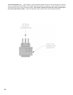
15. Install supplied air intake terminal. See Figure 16.
1. Do not exceed maximum vent length. Refer to
Table 4.
Horizontal –
2. Maintain minimum ¼ inch per foot slope in
horizontal runs. Position weld seams in vent pipes,
in all horizontal runs, at the top to avoid condensate
from lying on the seams.
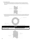
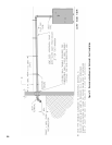
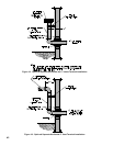
3 Recommended horizontal installation consists of
vent being sloped down away from boiler. See
Figure 12.
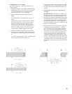
4. Alternate horizontal installation consists of vent
being sloped down toward the boiler. A horizontal
vent tee is required. See Figure 13.
5. Use appropriately designed thimbles when passing
through combustible walls (thimble use optional
for noncombustible walls). Insert thimble through
wall from outside. Secure outside ange to wall
with nails or screws, and seal with sealant material.
Install inside ange to inside wall, secure with nails
or screws, and seal with sealant material.
6. For noncombustible wall application when thimble
is not used, size opening such that female (bell) end
with locking band attached cannot pass through.
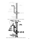
7. Join vent terminal to vent pipe. Locate vent
terminal between seventeen (17) inches and twenty-
nine (29) inches from wall when joined to inside
vent piping. See Figure 14.
8. Insert vent pipe through thimble/opening from
outside and join to vent system. Apply sealant
between vent pipe and opening/thimble to provide
weathertight seal.
Vertical –
10. Installation of a vertical vent drain tee is required
on all vertical vent applications. See Figure 6.
Attach vertical vent drain tee directly to elbow or
horizontal pipe from an elbow immediately after
vent connector.
H. Indoor Air Installation – See Figures 12, 13, 14, 15 and 16.