


41
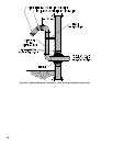
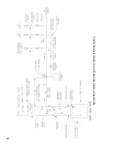
1. Do not exceed maximum vent/air intake lengths.
Refer to Table 4.
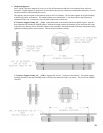
2. This installation will allow a maximum of seven (7)
feet vertical exterior run of the vent/air intake piping
to be installed on separate horizontal venting and
indoor air horizontal venting.
NOTICE
Exterior run to be included in equivalent vent/air
intake lengths.
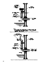
3. Install vent piping.
a. Install vent piping for desired venting system.
Refer to specic section for details for vent pipe
installation.
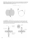
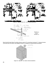
b. After penetrating wall/thimble, install an
AL 29-4C
®
90° elbow so that elbow leg is in the
up direction.
c. Install maximum of seven (7) feet of AL 29-4C
®
vent pipe. Refer to Sections C through E for proper
procedures for joining vent pipe and ttings.
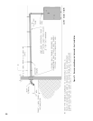
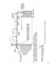
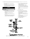
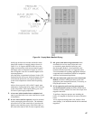
I. Optional Exterior Separate Horizontal Vent/Air Intake Terminal Mounting – See Figures 17, 18, 19, 20, 21 and 22.
d. At top of vent pipe length install an AL 29-4C
®
90° elbow so that elbow leg is opposite the
building’s exterior surface.
e. If installation requires indoor air, install
AL 29-4C
®
45° elbow to upper AL 29-4C
®
90°
elbow so that leg of 45° is in down direction (see
Figure 21 or 22). If not using indoor air, proceed
to Step f.
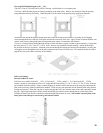
f. Install horizontal vent terminal (provided with
boiler).
g. Brace piping if required.
4. Air Intake Piping (not required for indoor air).
a. Install air intake piping for desired venting
system. Refer to specic section for details for
air intake installation.
b. After penetrating wall, install a corrosion
resistant 90
o
elbow so that elbow leg is in the up
direction.
c. Install maximum of seven (7) feet of corrosion
resistant air intake pipe.
d. At top of air intake pipe install air intake
terminal (provided with boiler).
e. Brace piping if required.
Figure 17: Optional Separate Horizontal Air 3” or 4” Intake Terminal Installation