


64
A. Safe operation and other performance criteria were
met with gas manifold and control assembly provided
on boiler when boiler underwent tests specied in
American National Standard for Gas-Fired Low-
Pressure Steam and Hot Water Boilers, ANSI Z21.13.
B. Verify that the venting, water piping, gas piping and
electrical system are installed properly. Refer to
installation instructions contained in this manual.
C. Conrm all electrical, water and gas supplies are
turned off at the source and that vent is clear of
obstructions.
D. Conrm that all manual shut-off gas valves between
the boiler and gas source are closed.
WARNING
Completely read, understand and follow all
instructions in this manual before attempting
start up.
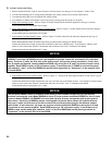
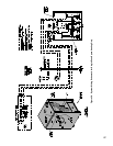
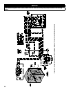
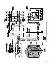
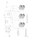
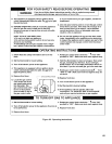
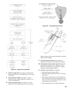
E. Fill entire heating system with water and vent air
from system. Use the following procedure on a Series
Loop or multi-zoned system installed as per Figure 25
or 26 to remove air from system when lling.
WARNING
The maximum operating pressure of this boiler
is 30 psig. Never exceed this pressure. Do not
plug or change pressure relief valve.
NOTICE
If it is required to perform a long term pressure
test of the hydronic system, the boiler should
rst be isolated to avoid a pressure loss due to
the escape of air trapped in the boiler.
To perform a long term pressure test including
the boiler, ALL trapped air must rst be removed
from the boiler.
A loss of pressure during such a test, with no
visible water leakage, is an indication that the
boiler contained trapped air.
1. Close full port ball valve in boiler supply piping.
2. Isolate all zones by closing zone valves or shut-off
valves in supply and return of each zone(s).
3. Attach a hose to the vertical hose bib located prior to
the full port ball valve in the system supply piping.
(Note - Terminate hose in ve gallon bucket at a
suitable oor drain or outdoor area).
4. Starting with one circuit at a time, open zone valve
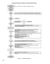
VIII. System Start-up
or shut-off valve in system supply and return piping.
5. Open hose bib.
6. Open ll valve (Make-up water line should be
located directly after full port ball valve in system
supply piping between air scoop and expansion
tank).
7. Allow water to overow from bucket until discharge
from hose is bubble free for 30 seconds.
8. Close the opened zone valve or shut-off valve for
the zone being purged of air, then open the zone
valve or shut-off valve for the next zone to be
purged. Repeat this step until all zones have been
purged. At completion, open all zone valves or
shut-off valves.
9. Close hose bib, continue lling the system until the
pressure gauge reads 12 psi. Close ll valve.
(Note - If make-up water line is equipped with
pressure reducing valve, system will automatically
ll to 12 psi. Follow ll valve manufacturer’s
instructions).
10. Open isolation valve in boiler supply piping.
11. Remove hose from hose bib.
F. Conrm that the boiler and system have no water
leaks.
G. Prepare to check operation.
1. Obtain gas heating value (in Btu per cubic foot)
from gas supplier.
2. Connect manometer to pressure tap on gas valve.
Use 1/8 NPT tapping provided.
3. Temporarily turn off all other gas-red appliances.
4. Turn on gas supply to the boiler gas piping.
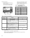
5. Conrm that the supply pressure to the gas valve is
14 in. w.c. or less. Refer to Table 5 for minimum
supply pressure.
6. Open the eld installed manual gas shut-off valve
located upstream of the gas valve on the boiler.
7. Using soap solution, or similar non-combustible
solution, electronic leak detector or other approved
method. Check that boiler gas piping valves, and
all other components are leak free. Eliminate any
leaks.
DANGER
Do not use matches, candles, open ames or
other ignition source to check for leaks.
8. Purge gas line of air.