


51
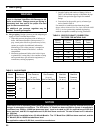
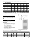
TABLE 7: MAXIMUM CAPACITY OF SCHEDULE 40 PIPE IN CFH* FOR NATURAL GAS PRESSURES
OF 0.5 PSIG OR LESS
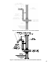
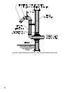
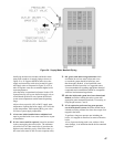
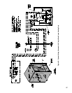
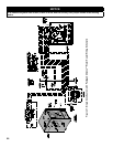
Figure 27: Recommended Gas Piping
TABLE 8: EQUIVALENT LENGTHS OF STANDARD PIPE FITTINGS & VALVES
B. Connect boiler gas valve to gas supply system.
WARNING
Failure to use proper thread compounds on all
gas connectors may result in leaks of ammable
gas.
WARNING
Gas supply to boiler and system must be
absolutely shut off prior to installing or servicing
boiler gas piping.
1. Use methods and materials in accordance with local
plumbing codes and requirements of gas supplier. In
absence of such requirements, follow National Fuel
Gas Code, NFPA 54/ANSI Z223.1.
2. Use thread (joint) compounds (pipe dope) resistant
to action of liqueed petroleum gas.
3. Install sediment trap, ground-joint union and manual
shut-off valve upstream of boiler gas control valve
and outside jacket. See Figure 27.
* 1 CFH of Natural Gas is approximately equal to 1 MBH; 1 CFH of LP is approximately equal to 2.5 MBH; con-
tact your gas supplier for the actual heating value of your gas.
Length
[Feet]
0.3 Inch w.c. Pressure Drop 0.5 Inch w.c. Pressure Drop
½ ¾ 1 1¼ ½ ¾ 1 1¼
10 132 278 520 1,050 175 360 680 1,400
20 92 190 350 730 120 250 465 950
30 73 152 285 590 97 200 375 770
40 63 130 245 500 82 170 320 660
50 56 115 215 440 73 151 285 580
60 50 105 195 400 66 138 260 530
70 46 96 180 370 61 125 240 490
80 43 90 170 350 57 118 220 460
90 40 84 160 320 53 110 205 430
100 38 79 150 305 50 103 195 400
VALVES FULLY OPEN
Pipe
Size
I.D.
Inches
Gate Globe Angle
Swing
Check
90°
Elbow
45°
Elbow
90° Tee, Flow
Through Run
90° Tee, Flow
Through Branch
½” 06.22 0.35 18.6 9.3 4.3 1.6 0.78 1.0 3.1
¾” 0.824 0.44 23.1 11.5 5.3 2.1 0.97 1.4 4.1
1” 1.049 0.56 29.4 14.7 6.8 2.6 1.23 1.8 5.3
1¼” 1.380 0.74 38.6 19.3 8.9 3.5 1.60 2.3 6.9