


23
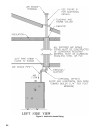
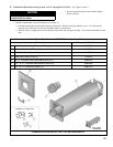
COMBINATION HORIZONTAL VENT SYSTEM COMPONENTS
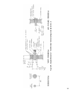
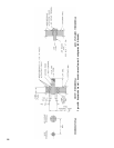
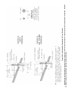
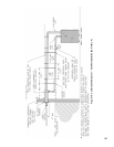
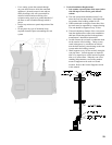
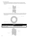
F. Combination Horizontal Venting System –SCG-3 Through SCG-6 ONLY – See Figures 10 and 11.
1. Do not exceed maximum vent/air intake lengths.
Refer to Table 4.
2.
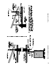
Install Combination Vent/Air Terminal. See Figure 11.
a. After determining the location with reference to Section B - General Venting Guidelines, cut a 6-1/8 inch square
opening in the wall for the air box sub-assembly which is 6 inch square.
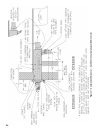
b. Remove and save shipping screw from end panel with collar and vent pipe assembly. This will be reinstalled in a later
step.
NOTICE
This vent system requires components not
supplied with the boiler.
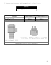
Vent Carton Part Number 61106012 (Includes Items Below)
Description Component Part Number
A Air Box Sub-Assembly (6” square x 2’ long) 61106011
B Exterior Wall Cover (10” square) 71106016
C 4” x 3” Vent Pipe Reducer 8116239
D Plate-Seal Exterior Cover (2) 71106017
E #8 x ½” Stainless Steel Sheet Metal Screw (19) 80860047
F #10 - 32 x ¼” Stainless Steel Machine Screw (8) 80860842
G #10 - 32 x ½” Aluminum Spacer (4) 80861617