


T874 MULTISTAGE THERMOSTATS AND Q674 SUBBASES
9 60-2485—8
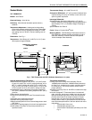
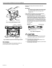
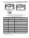
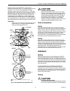
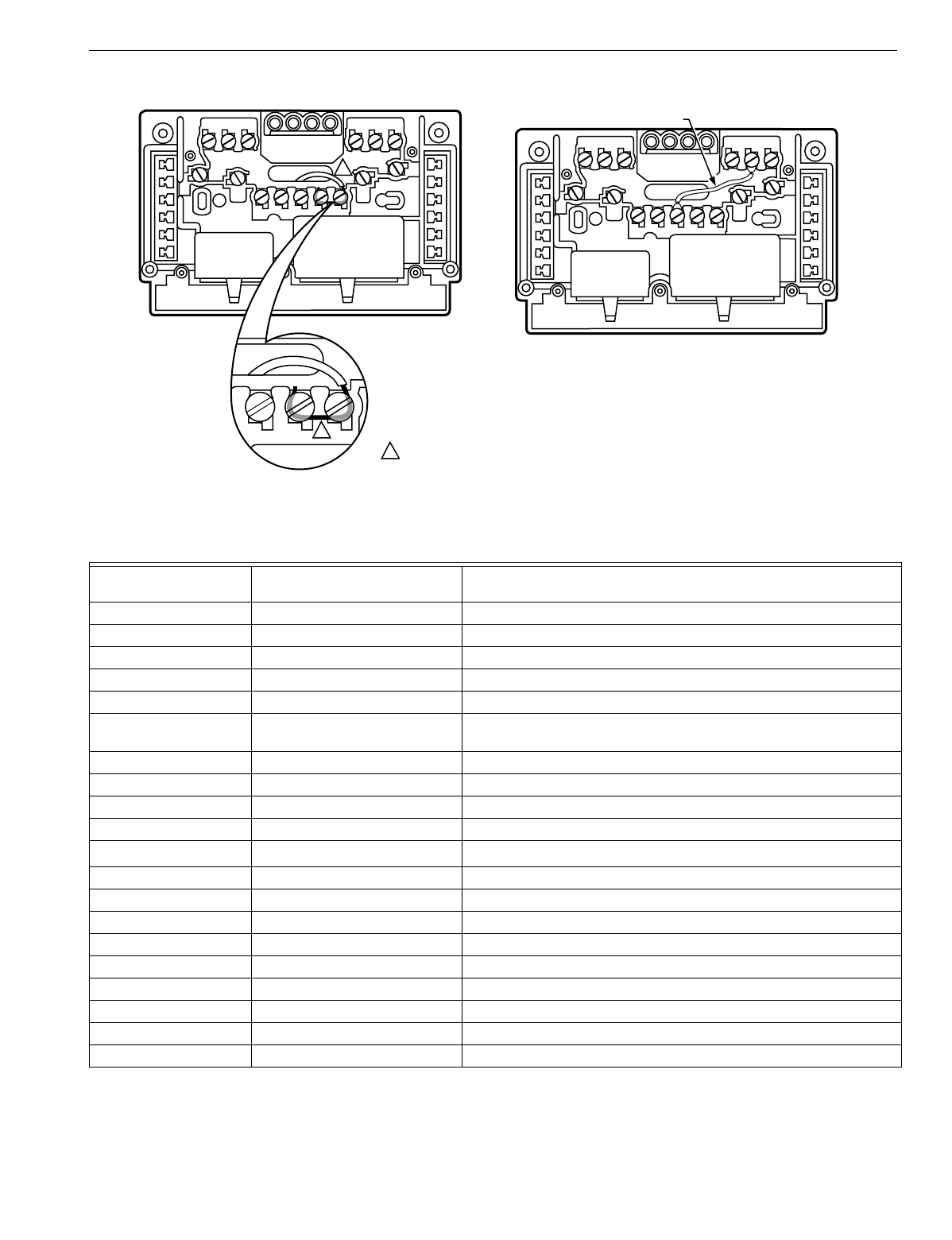
Fig. 8. Jumper adjacent terminals for special system hookup using stripped wire 3/4 in. (19 mm).
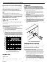
For nonadjacent terminals and using jumper wire supplied with subbase.
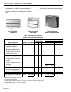
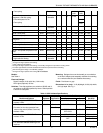
Table 5. Terminal Designations
a
Standard Terminal
Designation
Alternate Designations or
Customer Specials Typical Connection
BHeatin
g
damper motor; chan
g
eover valve
EKEmer
g
enc
y
heat rela
y
G F Fan rela
y
coil
LS
y
stem monitor
ORCoolin
g
damper motor; chan
g
eover valve
R V Power connection to transformer
(
internall
y
connected for heatin
g
and coolin
g)
RC Power connection to coolin
g
transformer
RH Power connection to heatin
g
transformer
W1 H1, R3 Sta
g
e 1 heatin
g
control
W2 H2, Y, R4 Sta
g
e 2 heatin
g
control
W3
Sta
g
e 3 heatin
g
control
b
Y1 C1, M Sta
g
e 1 coolin
g
control
Y2 C2 Sta
g
e 2 coolin
g
control
Y3 Sta
g
e 3 coolin
g
control
XX1,X2,CClo
gg
ed filter switch or common connection
T A Outdoor thermistor
L, C, H HSII control panel
PDefrost
O Momentar
y
circuit, chan
g
eover
A, A1, A2, Z, C, L LEDs
a
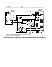
Other terminal desi
g
nations can be used that are not listed on this table. Refer to the hookup drawin
g
and internal schematic
for exact connections.
b
W3 controls the auxiliar
y
heat like W2, and allows addin
g
additional sta
g
es of auxiliar
y
heat with outdoor thermostats while
maintainin
g
the proper second sta
g
e anticipation.
M5899
1
1
1 TWO ADJACENT TERMINALS SHOWN JUMPERED ARE FOR EXAMPLE ONLY. COMPARE WIRING
DIAGRAM AND SUBBASE TO IDENTIFY TERMINALS TO BE JUMPERED.
JUMPER WIRE
(SUPPLIED WITH SOME MODELS)