


T874 MULTISTAGE THERMOSTATS AND Q674 SUBBASES
60-2485—88
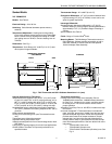
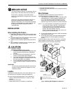
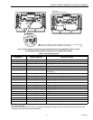
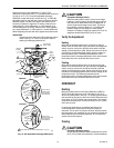
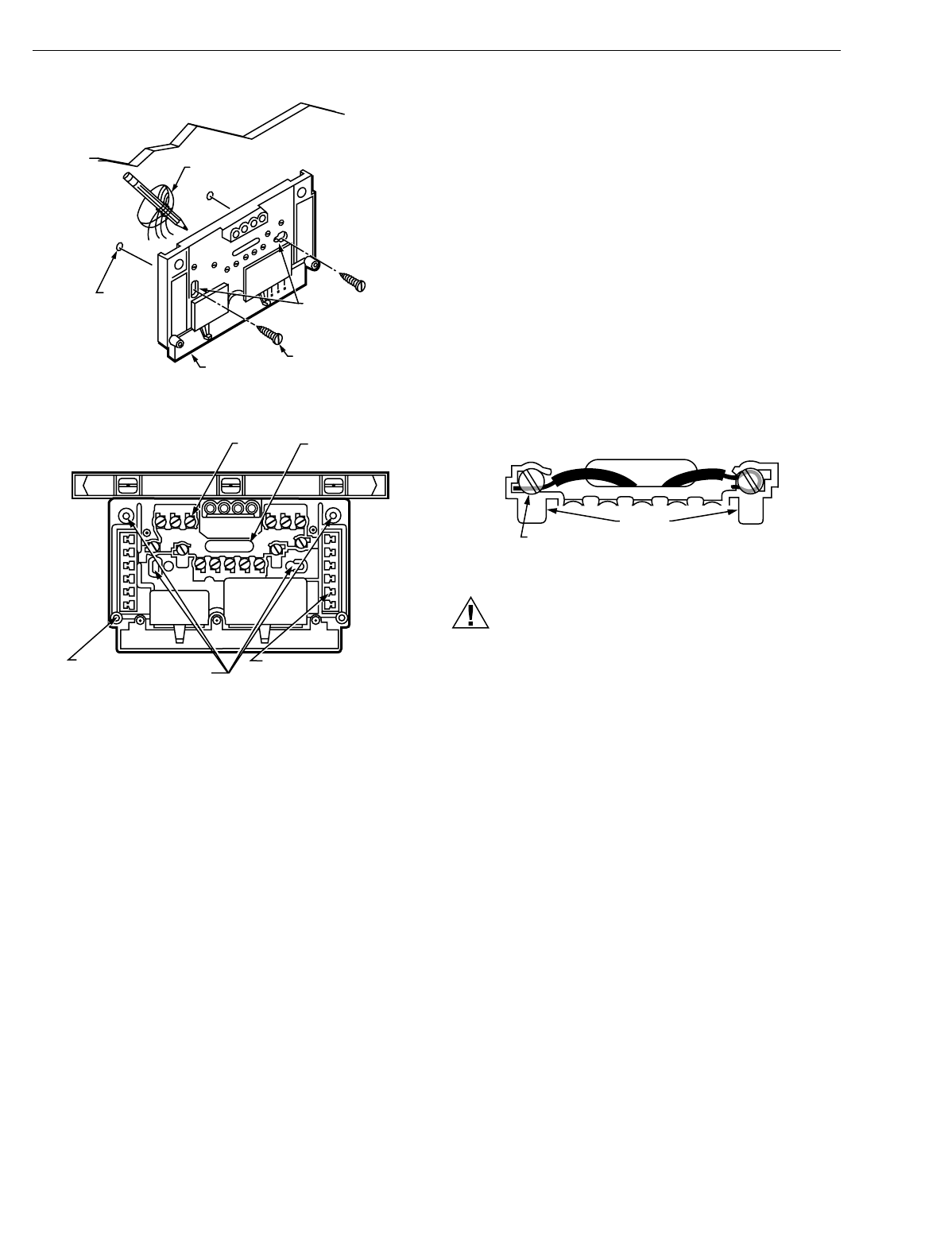
Fig. 5. Installing Q674 Subbase on wall.
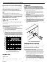
Fig. 6. Subbase components and leveling procedure.
Wire Subbase
Disconnect power suppl
y
before be
g
innin
g
installation to
prevent electrical shock or e
q
uipment dama
g
e.
All wirin
g
must compl
y
with local electrical codes and
ordinances.
IMPORTANT
Use 18 gauge, solid-conductor wire whenever possi-
ble. If using 18 gauge stranded wire, no more than
10 wires can be used. Do not use larger than
18 gauge wire.
Follow e
q
uipment manufacturer wirin
g
instructions when
available. To wire subbase, proceed as follows:
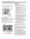
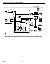
1.
Connect the s
y
stem wires to the subbase as shown in
the applicable dia
g
ram. A letter code is located near
each terminal for identification. T
y
pical terminal desi
g
-
nation and wirin
g
connections are listed in Table 5. The
terminal barrier permits strai
g
ht or wraparound wirin
g
connection. See Fi
g
. 7. The subbase can re
q
uire one or
more
j
umpers that ma
y
or ma
y
not be factor
y
-supplied.
See Fi
g
. 8 and the wirin
g
dia
g
rams for specific terminals
to be
j
umpered.
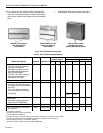
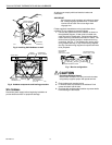
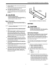
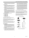
Fig. 7. Barrier configuration.
CAUTION
Equipment Damage Hazard.
Never install more than one wire per terminal unless
usin
g
factor
y
-supplied
j
umper with spade terminal.
2.
Firml
y
ti
g
hten each terminal screw.
3.
Fit wires as close as possible to the subbase. Push
excess wire back into the hole.
4.
Plu
g
hole with nonflammable insulation to prevent drafts
from affectin
g
the thermostat.
WIRES THROUGH
WALL OPENING
WALL
WALL
ANCHORS
(2)
SUBBASE
MOUNTING
SCREWS (2)
M926
MOUNTING
HOLES
SPIRIT LEVEL
M927
WIRING
TERMINAL
THERMOSTAT
CABLE OPENING
TO SPRING FINGER
CONTACTS ON
THE THERMOSTAT
(
UP TO 12
)
MOUNTING
HOLES (4)
POST FOR
MOUNTING
THERMOSTAT (2)
FOR STRAIGHT
INSERTION
–
STRIP 5/16 IN. (8 MM)
FOR WRAPAROUND–
STRIP 7/16 IN. (11 MM)
SUBBASE TERMINAL SCREW
M928
BARRIER