


T874 MULTISTAGE THERMOSTATS AND Q674 SUBBASES
15 60-2485—8
thermostats. The schematics can be field-modified as
re
q
uired
(
EX: if T874C is bein
g
used, eliminate second
sta
g
e of heat
)
.
For heat pump circuits:
Cool chan
g
eover valve—operates on coolin
g
. The revers-
in
g
valve or rela
y
is activated either b
y
movin
g
the s
y
s-
tem switch to COOL
(
manual chan
g
eover
)
or b
y
a
mercur
y
switch that makes on a temperature rise
(
auto
chan
g
eover
)
.
Heat chan
g
eover valve—operates on heatin
g
. The revers-
in
g
valve or rela
y
is activated either b
y
movin
g
the s
y
s-
tem switch to HEAT
(
manual chan
g
eover
)
or b
y
a
mercur
y
switch that makes on a temperature fall
(
auto
chan
g
eover
)
.
S
y
stem monitor rela
y
—optional e
q
uipment on some heat
pumps includes an R4222P1065 or e
q
uivalent. This
s
y
stem monitor rela
y
detects a malfunction in the com-
pressor and indicates the malfunction b
y
activatin
g
the
EMERGENCY HEAT LED on the Q674 Switchin
g
Sub-
base. The s
y
stem monitor rela
y
is usuall
y
wired into the
L terminal on the Q674.
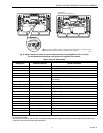
Each mercur
y
switch is identified b
y
function:
H1—Sta
g
e 1 Heatin
g
.
H2—Sta
g
e 2 Heatin
g
.
H3—Sta
g
e 3 Heatin
g
.
C1—Sta
g
e 1 Coolin
g
.
C2—Sta
g
e 2 Coolin
g
.
C3—Sta
g
e 3 Coolin
g
.
C/O—Chan
g
eover
(
heat pumps
)
.
Each anticipator is identified and each switch affected is
named
(
EX: H1 anticipator, C1 anticipator
)
.
All T874 Multista
g
e Thermostats use mercur
y
switches. Each
schematic indicates switch operation b
y
bein
g
drawn in the
open position with an arrow indicatin
g
operation with a
temperature RISE or FALL.
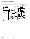
One circuit has been selected that is t
y
pical of various models
used with heat pumps. This circuit has been traced to
illustrate the functions performed b
y
these control s
y
stems.
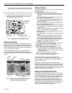
Tracing Method:
1.
Alwa
y
s be
g
in at the s
y
stem transformer or R terminal.
You ma
y
want to draw the switch contacts in each
switch position to aid in tracin
g
. Colored pencils are
helpful when onl
y
one cop
y
of the circuit is available.
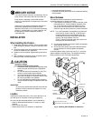
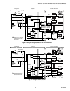
See Fi
g
. 16 for a description of the hookup s
y
mbols and
Fi
g
. 17 throu
g
h 25 for t
y
pical hookups.
2.
Completel
y
trace onl
y
one circuit at a time
(
for example:
heat or cool
)
.
3.
Connections are indicated b
y
small dots at the point of
intersection. If there is no dot, there is no connection.
4.
The left portion of the circuit
(
the thermostat
)
contains
the mercur
y
switches. The heat switches make on a
temperature fall, and the cool switches make on a tem-
perature rise. Fixed anticipation is represented b
y
a zi
g
-
za
g
line and ad
j
ustable anticipation is a zi
g
za
g
with an
arrow. The resistance of the fixed anticipator is so lar
g
e
it limits current so that a s
y
stem rela
y
cannot be pulled
in from a circuit path
g
oin
g
throu
g
h the fixed anticipator.
The rela
y
can be pulled in throu
g
h an ad
j
ustable antici-
pator because its resistance is
g
enerall
y
0 to 5 ohms.
5.
The center portion
(
the subbase
)
contains the switches.
The fan switch is above the s
y
stem switch. The small
circles on the switch represent the maximum possible
contacts available on the Q674 Subbase. The lar
g
er cir-
cles represent the switch positions available on this par-
ticular Q674, with the solid circle representin
g
where it
is actuall
y
switched on the dia
g
ram.
NOTE: Solid circles are not interconnected electricall
y
.
At the ri
g
ht, the rela
y
s and contactors are shown, attached to
the proper terminals. The terminals are represented b
y
lar
g
e
circles with terminal desi
g
nations in capital letters. See Table
3 for the meanin
g
of each lettered terminal.
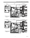
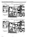
Sometimes power for a fixed anticipator is brou
g
ht throu
g
h an
off s
y
stem rela
y
like the chan
g
eover rela
y
shown in Fi
g
. 20.
This current is kept low b
y
the hi
g
h resistance of the fixed
anticipator so that rela
y
does not pull in.
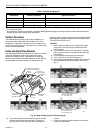
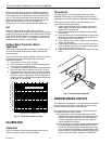
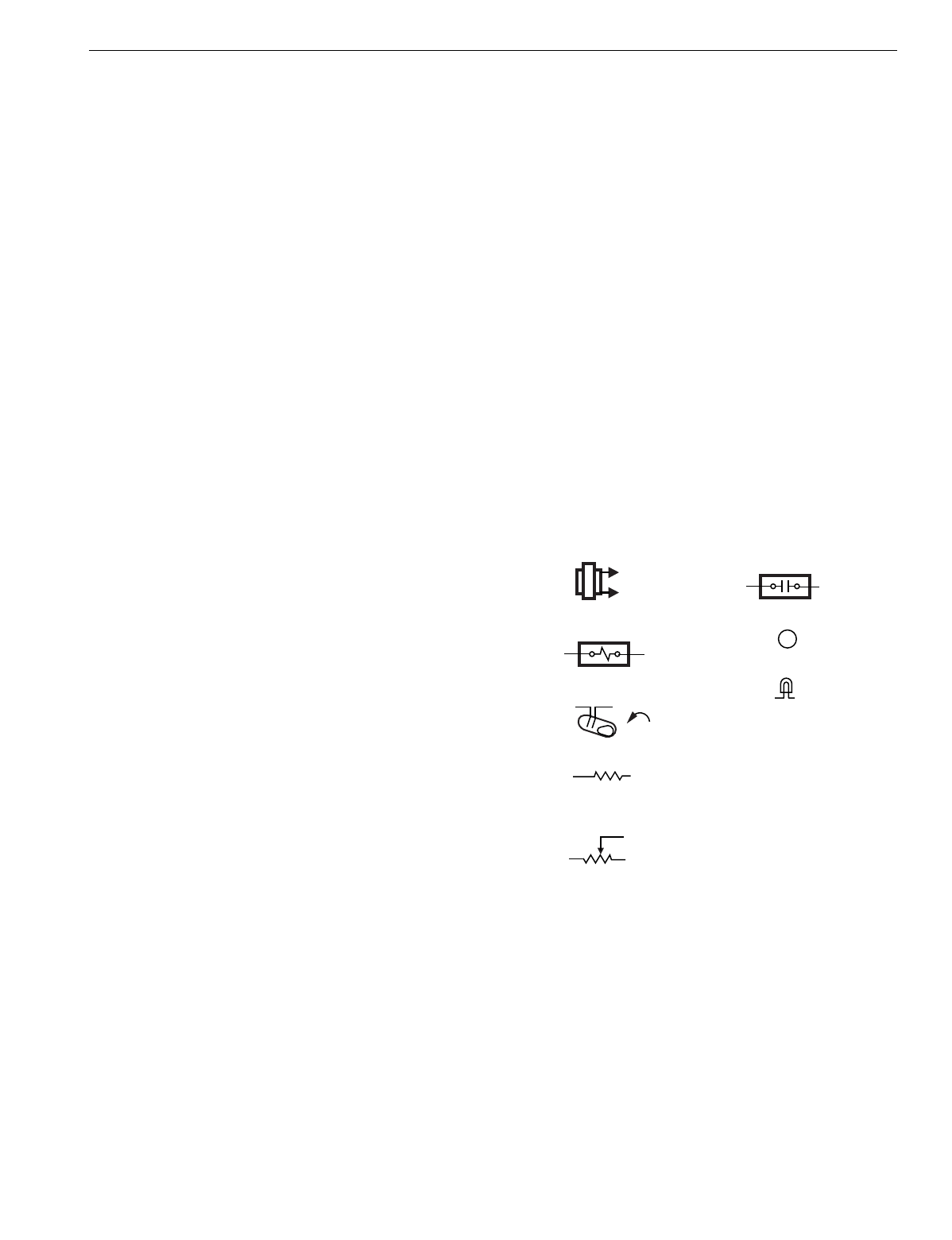
Fig. 16. Key to hookup symbols.
M5848
KEY TO HOOKUP SYMBOLS
TRANSFORMER
(24 VAC SECONDARY)
RELAY/CONTACTOR CONTACTS
LED
RELAY OR CONTACTOR COIL
MERCURY SWITCH
FIXED ANTICIPATOR
HIGH RESISTANCE
(TYPICALLY 5 KILOHMS)
ADJUSTABLE ANTICIPATOR
LOW RESISTANCE
(TYPICALLY 0 TO 5 OHMS)
TERMINAL
ODT
OUTDOOR THERMOSTAT
EHR
EMERGENCY HEAT RELAY
RTD
TIME DELAY RELAY
RD
DEFROST RELAY
CHP
PRESSURE SWITCH
LACO
LOW AMBIENT CUTOFF
B