


T874 MULTISTAGE THERMOSTATS AND Q674 SUBBASES
13 60-2485—8
Each mark on the scale represents 1°F
(
0.6°C
)
The
differential is factor
y
set at 2°F
(
1°C
)
the differential can be set
as hi
g
h as 12°F
(
7°C
)
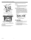
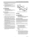
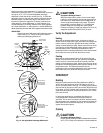
To set the ad
j
ustable intersta
g
e
differential, loosen the tension screw. See Fi
g
. 13. Slide the
ad
j
ustable scale to ali
g
n with the number of de
g
rees desired
between sta
g
es. Use the lower ed
g
e of the tension screw
bracket as a
g
uide for ali
g
nment. In heatin
g
, slide the lever
wider
apart for a
larger
differential, or
closer
to
g
ether for a
smaller
differential. In coolin
g
, slide the lever
closer
to
g
ether
for a
larger
differential, or
wider
apart for a
smaller
differential.
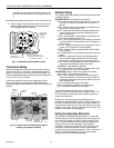
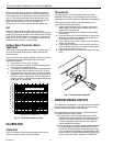
While supportin
g
the scale with hand, ti
g
hten the tension screw.
IMPORTANT
Support the scale with hand while tightening tension
screw. See Fig. 13. Failure to do so can result in
twisting and damaging bimetal coil.
Fig. 13. Set adjustable interstage differential.
CAUTION
Equipment Damage Hazard.
When the thermostat is used to control a two-sta
g
e
heatin
g
or coolin
g
s
y
stem, the second sta
g
e mercur
y
bulb must never make before the first sta
g
e bulb, or
severe e
q
uipment dama
g
e could result. To prevent
this problem, provide at least 2°F
(
1°C
)
differential
between sta
g
e-one and sta
g
e-two make points.
Example: in heatin
g
, if sta
g
e-one makes at 70°F
(
21°C
)
sta
g
e-two should make at 68°F
(
20°C
)
or lower.
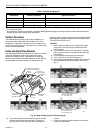
Verify the Adjustment
Heating
Start with the heatin
g
setpoint lever all the wa
y
to the left.
Slowl
y
move the lever to the ri
g
ht,
j
ust until the first sta
g
e bulb
makes
(
mercur
y
rolls to the ri
g
ht side of the bulb
)
. Note the
settin
g
on the temperature scale. Slowl
y
move the lever to the
ri
g
ht until the second sta
g
e bulb makes. Note the settin
g
on
the temperature scale. The difference between the two
temperatures is the
interstage differential,
which should match
the number set on the scale with the tension screw.
Cooling
Start with the coolin
g
setpoint lever all the wa
y
to the ri
g
ht.
Slowl
y
move the lever to the left,
j
ust until the first sta
g
e bulb
makes
(
mercur
y
rolls to the left side of the bulb
)
. Note the
settin
g
on the temperature scale. Slowl
y
move the lever to the
left until the second sta
g
e bulb makes. Note the settin
g
on the
temperature scale. The difference between the two
temperatures is the
interstage differential,
which should match
the number set on the scale with the tension screw.
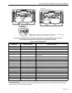
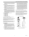
CHECKOUT
Heating
Move the s
y
stem switch on the Q674 Subbase to HEAT or
AUTO. Move the heat lever on the T874 about 10°F
(
6°C
)
above room temperature. See Fi
g
. 12. Heatin
g
s
y
stem should
start and the fan should run after a short dela
y
. Move the heat
lever about 10°F
(
6°C
)
below room temperature. The heatin
g
e
q
uipment should shut off, and the fan should run for a short
time, then shut off.
In heat pump applications, sometimes time dela
y
s are
involved before the compressor and auxiliar
y
heat are
activated. This is due to a minimum-off timer, which prevents
the compressor from restartin
g
for five minutes from when the
thermostat last turned off the compressor, or from when the
s
y
stem first received power.
Cooling
CAUTION
Equipment Damage Hazard.
Do not operate coolin
g
if outdoor temperature is below
50°F
(
10°C
)
. Refer to manufacturer recommendations.
TENSION
SCREW
ALIGN LOWER
EDGE WITH
SCALE
NOTCH
10°F
SCALE
1
SLIDE LEVER
WIDER APART
FOR LARGER
DIFFERENTIAL
HEATING
TENSION
SCREW
ALIGN LOWER
EDGE WITH
SCALE
NOTCH
4°F
SCALE
1
SLIDE LEVER
CLOSER TOGETHER
FOR LARGER
DIFFERENTIAL
COOLING
1 EACH MARK ON THE SCALE REPRESENTS 1°F (0.6°C).
M937
1.2
.8
.6
.3
.2
1
.5
.4
50 60
70 80
HEAT
TENSION
SCREW
HEATING SET-
POINT LEVER
FIRST
STAGE
SWITCH
SECOND STAGE
(ADJUSTABLE)
SWITCH
SCALE