


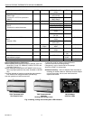
T874 MULTISTAGE THERMOSTATS AND Q674 SUBBASES
60-2485—810
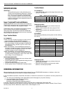
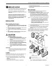
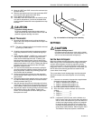
Outdoor Disconnect
The National Electrical Code re
q
uires the installation of a
disconnect switch w
ithin
si
g
ht of the outdoor unit of an air
conditioner or heat pump. The switch is for the safet
y
of an
y
technician workin
g
on the unit. The technician can assure that
the unit
remains
unpowered.
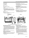
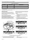
Install and Adjust Stop Brackets
The stop brackets should be installed onl
y
if there is a need to
restrict the ad
j
ustable ran
g
e of the heatin
g
and coolin
g
temperature setpoint levers. If ad
j
ustable lever stops are
desired, order 4074ECK Envelope Assembl
y
, which contains
two ad
j
ustable lever stop brackets, one brass insert, one
mountin
g
screw and two lockin
g
screws with insulated heads.
When installed, the stop brackets limit the movement of the
T874 HEAT and COOL levers.
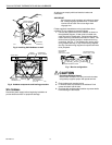
TO INSTALL:
1.
Remove the thermostat cover b
y
pullin
g
the bottom
ed
g
e of the cover upward until it snaps free of the
mountin
g
slots.
2.
Turn to the back of the T874 Thermostat. Locate the
hole for the brass insert in the plastic base below the
LED window.
3.
Push the brass insert into the hole with fin
g
er.
4.
Turn to the front of the T874 Thermostat.
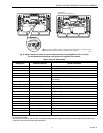
5.
Place the two stop brackets in position with the tabs in
the slot between the HEAT and COOL levers. See
Fi
g
. 9.
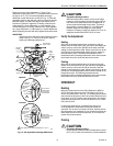
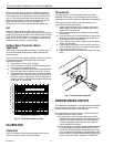
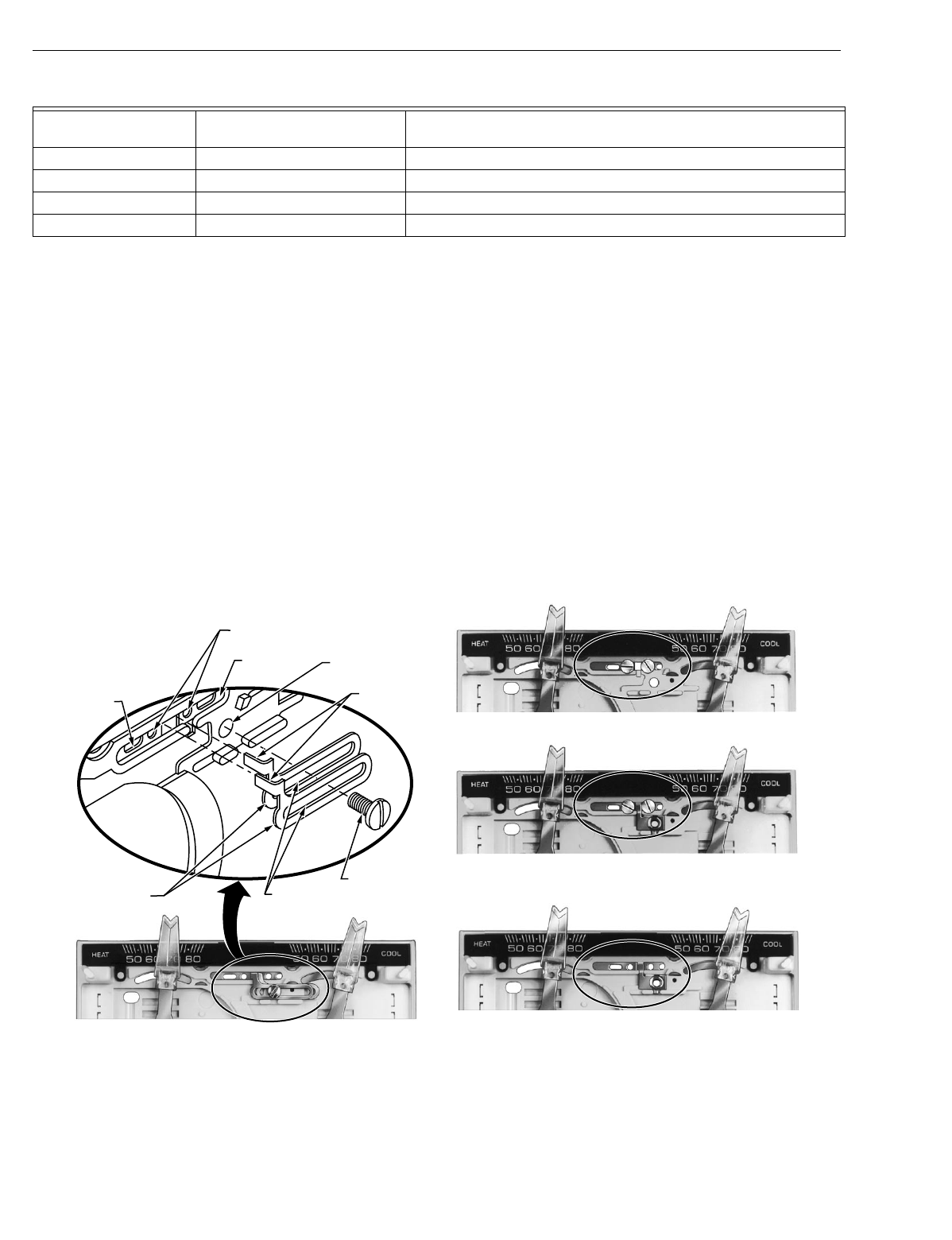
Fig. 9. Range limiting and lever locking methods.
6.
Insert the mountin
g
screw into the two slots in the stop
brackets and attach to the brass insert. Ti
g
hten the
screw to pull the brass insert into the back of the ther-
mostat.
7.
Loosen the mountin
g
screw enou
g
h to free the stop
brackets for ad
j
ustment.
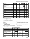
T External temperature readout, T rela
y
R1, R2 LO and HI speed fan rela
y
s
RS Coolin
g
contactor
Y M Compressor contactor
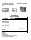
Table 5. Terminal Designations
a
Standard Terminal
Designation
Alternate Designations or
Customer Specials Typical Connection
a
Other terminal desi
g
nations can be used that are not listed on this table. Refer to the hookup drawin
g
and internal schematic
for exact connections.
b
W3 controls the auxiliar
y
heat like W2, and allows addin
g
additional sta
g
es of auxiliar
y
heat with outdoor thermostats while
maintainin
g
the proper second sta
g
e anticipation.
HEAT
LEVER
HOLES FOR INSULATED
LOCKING LEVER SCREWS
COOL
LEVER
HOLE WITH
BRASS INSERT
BRACKET
TABS
ADJUSTABLE
LEVER STOP
BRACKETS
BRACKET
SLOTS
MOUNTING
SCREW
ADJUSTABLE STOPS
ADJUSTABLE LOCKING LEVERS
NONADJUSTABLE STOPS
WITH LOCKING LEVER SCREWS
75°F (24°C) MAX. HEAT
75°F (24°C) MIN. COOL
NONADJUSTABLE D.O.D. STOPS
72°F (22°C) MAX. HEAT
78°F
(
26°C
)
MIN. COOL
M7626