


T874 MULTISTAGE THERMOSTATS AND Q674 SUBBASES
60-2485—822
CAUTION
Equipment Damage Hazard.
Due to calibration techni
q
ues used for T874
Thermostats with outdoor reset, the C815A Thermistor
must be wired into the s
y
stem at all times. Failure to
do so will result in serious de
g
radation of performance.
Service and Replacement of C815A Outdoor
Thermistor
To check and verif
y
thermistor operation, perform the
followin
g
steps:
1.
Disconnect wire from T terminal on subbase.
2.
Measure resistance with ohmmeter across the T sub-
base wire and X subbase terminal.
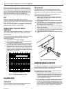
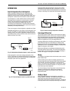
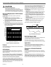
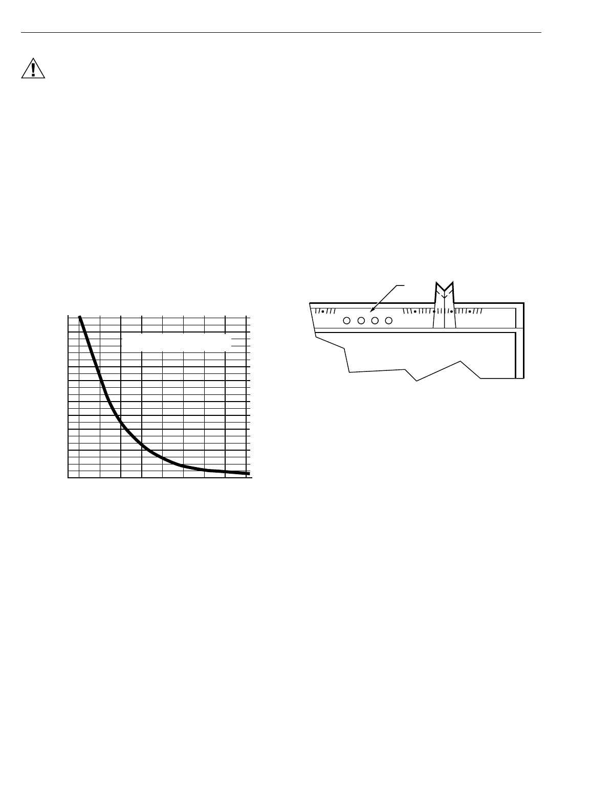
3.
Take outdoor temperature measurement at thermistor
location and find correct thermistor resistance on the
chart in Fi
g
. 29.
4.
Compare resistance on the chart with measured resis-
tance. Replace C815A if resistance varies more than 15
percent. Contact installin
g
dealer for packa
g
ed replace-
ment outdoor thermistor.
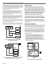
Fig. 29. Thermistor resistance chart.
Features
Two of the features of the T874/Q674 include LED indicators
and restricted setpoint.
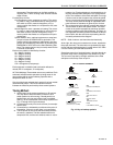
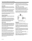
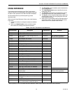
LED Indicators
The li
g
ht-emittin
g
diodes
(
LED
)
indicators on the subbase
li
g
ht on command when somethin
g
specific happens in the
s
y
stem. See Fi
g
. 30.
Up to four different LEDs are available. The thermostat has a
clear lens window for viewin
g
each LED. On TRADELINE
models, a small insert is used so the LED function desired can
be selected.
This must be done during installation.
A blank insert is factor
y
-installed in some T874 models. To
remove it, push both temperature settin
g
levers to the far ends
of the thermostat. Use index fin
g
ernail to
g
entl
y
pull out the
scaleplate a fraction of an inch. Turn thermostat upside-down,
and the blank insert falls out.
A strip of four inserts is included with TRADELINE T874. Drop
a strip into the recessed area behind the scaleplate so
selected LEDs show. Make sure insert is completel
y
seated in
recessed area. Let scaleplate pop back; then set levers to
desired position.
• FILTER LED li
g
hts when the filter is clo
gg
ed and needs
replacement.
• CHECK LED li
g
hts when somethin
g
needs to be checked
or done to maintain efficient operation of s
y
stem. See
heatin
g
s
y
stem instructions for CHECK LED meanin
g
.
• EM. HT. LED li
g
hts when the emer
g
enc
y
heat is operatin
g
.
• SUPL. HT. LED li
g
hts when the supplemental heat is
operatin
g
.
• LOCKOUT LED li
g
hts when the s
y
stem is shut down and
needs maintenance.
• AUXILIARY HEAT LED li
g
hts when the auxiliar
y
heat is
operatin
g
.
• SERVICE or MALFUNCTION LED can have several
meanin
g
s. Consult heatin
g
s
y
stem instructions.
LEDs cannot be replaced or added in the field.
Fig. 30. T874/Q674 LED location.
Restricted Setpoint (DoD)
The Department of Defense
(
DoD
)
models are e
q
uipped with
a restricted setpoint feature for fuel efficienc
y
.
Fixed stops are factor
y
-set so setpoint levers cannot be set
above 72°F
(
22°C
)
on heatin
g
, or below 78°F
(
26°C
)
on coolin
g
.
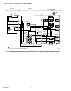
Applications
The T874/Q674 can be applied to standard residential
s
y
stems for automatic or manual chan
g
eover, to commercial
rooftop applications, or to heat pump applications.
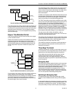
Changeover on Standard Residential
Systems
In a standard residential heatin
g
-coolin
g
circuit, chan
g
eover
between heatin
g
and coolin
g
can be done either automaticall
y
or manuall
y
.
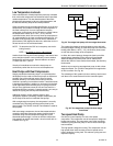
Automatic chan
g
eover is done b
y
an AUTO position on the
subbase s
y
stem switch. See Fi
g
. 31. When the switch is in the
AUTO position, the thermostat automaticall
y
chan
g
es between
heat and cool modes, dependin
g
on the indoor temperature.
THERMISTOR RESISTANCE (ohms)
C815A THERMISTOR RESISTANCE
R = 400 ohms ± 10% AT 77°F (25°C)
4600
4400
4200
4000
3800
3600
3400
3200
3000
2800
2600
2400
2200
2000
1800
1600
1400
1200
1000
800
600
400
200
0
-20 0 20 40 60 80 100 120 140
TEMPERATURE OF THERMISTOR (°F)
M1590A
80
50 60 70 80
COOL
EM.
HEAT
FILTER SERV.
AUX
HEAT
M5830
LEDS