


T874 MULTISTAGE THERMOSTATS AND Q674 SUBBASES
27 60-2485—8
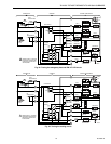
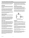
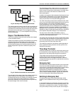
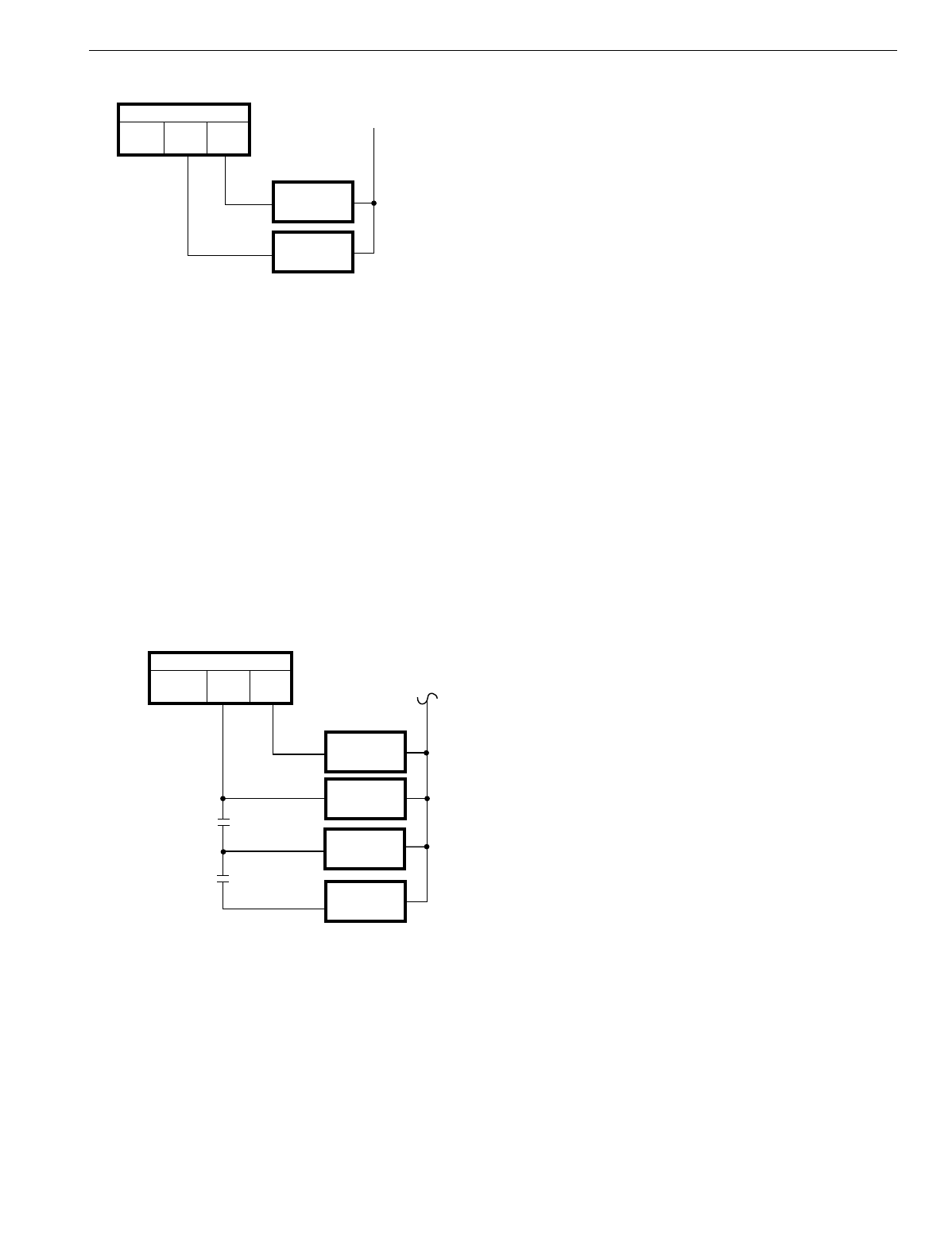
Fig. 39. Auxiliary heat in two-stage thermostat.
This method keeps the auxiliar
y
heat off until the heatin
g
load
is lar
g
e enou
g
h to demand 100 percent heat pump operation.
That demand is measured b
y
the thermostat and is the actual
heat re
q
uirement of the space. The two-sta
g
e thermostat
re
q
uires about a 2°F
(
1.1°C
)
room temperature drop to brin
g
on the second sta
g
e.
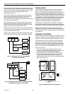
Stage or Time Modulated Control
There are two different wa
y
s to control auxiliar
y
heat, sta
g
ed
or time modulated control.
Outdoor thermostats
are used to switch additional increments
of electric heat into the thermostat circuit as the outdoor
temperature
g
ets lower. All increments of auxiliar
y
heat are
still controlled b
y
sta
g
e-two of the thermostat but onl
y
if the
outdoor temperature re
q
uires the additional capacit
y
. See
Fi
g
. 40.
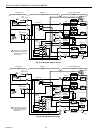
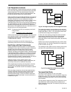
Fig. 40. Outdoor thermostats for auxiliary heat.
The rationale for this s
y
stem is that it ver
y
closel
y
matches the
s
y
stem capacit
y
to the heatin
g
load of the buildin
g
. B
y
calculatin
g
the heat loss of a buildin
g
, the installin
g
contractor
can pick the theoretical outdoor temperature at which to
permit each additional unit of electric heat to be operated b
y
the second sta
g
e of the room thermostat.
The disadvanta
g
e of this s
y
stem is that it can re
q
uire several
outdoor thermostats. Also, since the unit is operatin
g
most
often at nearl
y
full capacit
y
, the thermostat is on lon
g
er which
results in more droop, with a little more offset from the
thermostat setpoint.
In addition, the capacit
y
is tied to theoretical load, based on heat
loss calculations. Normall
y
this is ver
y
close to the actual load,
but there are times where the second sta
g
e is switched on too
soon
(
no harm done
)
or too late
(
the buildin
g
g
ets cold
)
.
The T874 Thermostat produces
time modulated
control, which
is the on time of the thermostat chan
g
in
g
durin
g
each c
y
cle as
the load chan
g
es. The on time of the heatin
g
s
y
stem is
directl
y
proportional to the heatin
g
load of the buildin
g
. As an
example of the
q
ualit
y
of time modulated control, consider the
t
y
pical
g
as furnace. It can have a capacit
y
of 100,000 Btu
(
293 kW
)
, which is controlled On-Off. The output is 100,000 Btu
(
293 kW
)
or nothin
g
. A
q
ualit
y
thermostat controls so closel
y
that
the occupants rarel
y
detect chan
g
es in room temperature.
The same is true with 50,000 or 60,000 Btu
(
146.5 or
178.8 kW
)
of heat pump auxiliar
y
electric heat. The T874 can
provide the same hi
g
h
q
ualit
y
control.
This scheme also eliminates the need for outdoor thermostats
and thus offers the manufacturer an opportunit
y
to reduce unit
cost. One disadvanta
g
e is that a
thermostat jiggler
can be
demandin
g
more kW of strip heat when chill
y
.
The method an
y
particular manufacturer selects depends on
which ar
g
uments it finds persuasive and the opinions of its
distributors and dealers.
Three-Stage Thermostat
A definite improvement in
q
ualit
y
of control and econom
y
can
be achieved with a three-sta
g
e thermostat
(
T874W
)
, which is
especiall
y
true with heat pumps usin
g
dual compressors.
Three-sta
g
e control permits both the heat pump and the
auxiliar
y
heat to be tied directl
y
to the demand of the
controlled space. With a two-sta
g
e compressor, maximum
(
100 percent
)
heat pump operation is re
q
uired before auxiliar
y
heat is brou
g
ht on.
Emergency Heat
Some provision is
g
enerall
y
re
q
uired to back up the compressor
in the event of a failure durin
g
the heatin
g
season. In fact, it is
q
uite common to find that local buildin
g
codes or electric utilities
re
q
uire that a specified percent of the buildin
g
heatin
g
re
q
uirements be available from emer
g
enc
y
heat—a source
other than the heat pump compressor. Almost universall
y
, the
source is electric resistance heaters. T
y
picall
y
, the re
q
uirement
is for 70 or 80 percent of the buildin
g
heatin
g
needs.
Switching to Emergency Heat
Conventional heat pump control
(
thermostat lo
g
ic
)
usuall
y
includes a manual subbase switch to brin
g
on the emer
g
enc
y
heat.
In one control strate
gy
, the
emergency heat
rela
y
is turned on
b
y
the EM.HT. selector switch on the thermostat subbase. The
compressor is prevented from runnin
g
. The electric heaters
are c
y
cled as the
y
normall
y
would be b
y
the
second stage
of
M5836
COMPRESSOR
CONTRACTOR
THERMOSTAT
HEAT 2
HEAT 1
AUXILIARY
HEAT RELAY
CONTROLS
AT 65°F (18°C)
CONTROLS
AT 63°F (17°C)
M5834
COMPRESSOR
CONTACTOR
THERMOSTAT
HEAT 2
HEAT 1
AUXILIARY
HEAT RELAY 1
AUXILIARY
HEAT RELAY 2
AUXILIARY
HEAT RELAY 3
OUTDOOR
THERMOSTATS
20°F
(-7°C)
5°F
(-15°C)