


T874 MULTISTAGE THERMOSTATS AND Q674 SUBBASES
3 60-2485—8
Standard Models
T874 THERMOSTATS
Models:
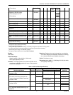
See Table 3.
Electrical Rating:
24 to 30 Vac.
Switching:
Coiled bimetal elements operate mercur
y
switches.
Temperature Adjustment:
Heatin
g
and coolin
g
settin
g
levers, with separate scales located on top of thermostat
base. Common lever for heatin
g
and coolin
g
on T874R;
one coolin
g
lever on T874E,V; and one heatin
g
lever on
T874F,Q.
Dimensions:
See Fi
g
. 1.
Temperature:
Scale Ran
g
e: 42° to 88°F
(
6° to 31°C
)
stan-
dard; optional ran
g
es available.
Thermometer Range:
42° to 88°F
(
6 to 31°C
)
Changeover Differential:
4°F
(
2°C
)
minimum between heat-
in
g
and coolin
g
(
5°F [3°C] on T874W
)
. Levers can be set
apart for
g
reater separation.
Interstage Differential:
Standard Models: Mechanical differential is 1°F
(
0.6°C
)
between heatin
g
or coolin
g
sta
g
es; operatin
g
differential is
approximatel
y
1.9°F
(
1°C
)
between sta
g
es in heatin
g
or
coolin
g
.
Special Models: See Table 3.
Finish:
Bei
g
e or Premier White
®
finish.
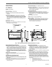
Mounting Means:
T874 Multista
g
e Thermostat mounts on
Q674 Subbase. Subbase mounts horizontall
y
on wall or
outlet box. Mounts on vertical outlet box with optional
193121A Adapter Plate Assembl
y
.
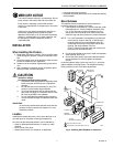
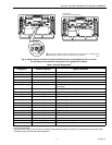
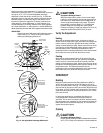
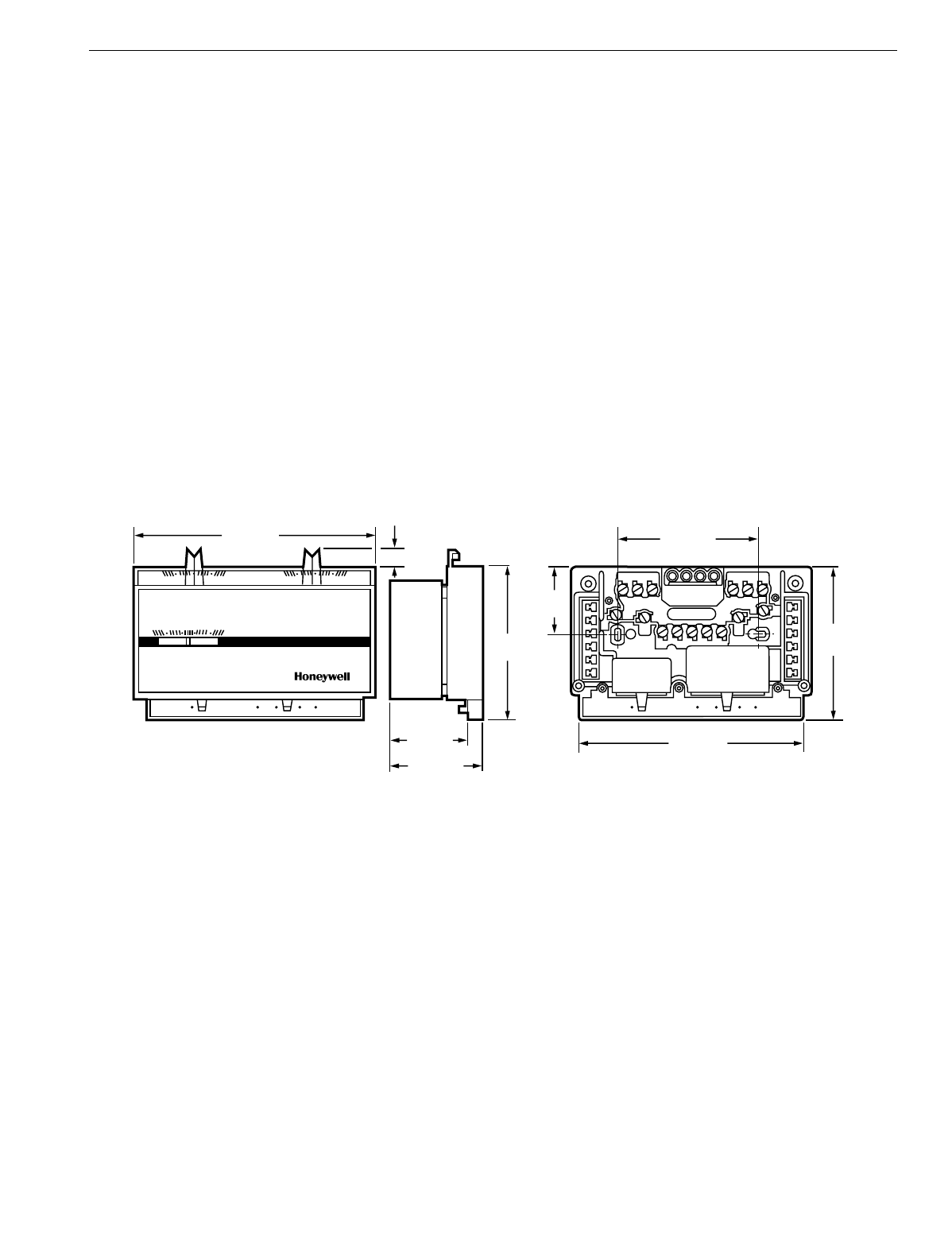
Fig. 1. T874 Thermostat and Q674 Subbase dimensions in in. (mm).
Optional Specifications (T874 Only):
Temperature scale ran
g
es are 40° to 75°F
(
4° to 24°C
)
heat-
in
g
and 75° to 90°F
(
24° to 32°C
)
coolin
g
with stop; 44° to
68°F
(
7° to 20°C
)
heatin
g
, 80° to 86°F
(
27° to 30°C
)
cool-
in
g
; 6° to 29°C
(
43° to 85°F
)
Celsius scale; 3° to 22°C
(
38°
to 72°F
)
and 26° to 32°C
(
78° to 90°F
)
coolin
g
with stop.
Nonad
j
ustable factor
y
-added stop limits heatin
g
setpoint to
72°F
(
22°C
)
maximum and coolin
g
setpoint to 78°F
(
26°C
)
minimum.
OEM customer personalization.
Lockin
g
cover and lockin
g
lever
(
see Thermostat Accesso-
ries
)
.
Thermostat cover without thermometer.
Ad
j
ustable lockin
g
temperature stops.
Volta
g
e heat anticipation for first or second sta
g
e heat or both.
See Table 3.
Fast c
y
clin
g
on heatin
g
sta
g
e
(
s
)
for electric heat applications.
C815A Outdoor Thermistor for improved performance on
specified models.
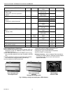
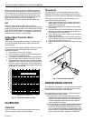
Thermostat Accessories:
Lockin
g
Cover and Lockin
g
Lever Assembl
y
: Part no.
194559R with thermometer; 194559S without thermome-
ter. See Fi
g
. 2. Includes cover, screws, and Allen wrench
for lockin
g
cover. The screws must be used to assure
proper operation.
Ad
j
ustable Lever Stop: Part no. 4074ECK; includes lever stop
and screws.
Universal Versa
g
uard™ Thermostat Guard: Includes wall-
plate, rin
g
base,
g
uard cover, tumbler lock, two ke
y
s and
optional Hone
y
well lo
g
o insert. Double-wall construction
provides extra measure of tamper-resistance. Tamper-
resistant lock; ke
y
cannot be removed without bein
g
in
locked position. Vents in
g
uard base allow airflow for opti-
mum thermostat performance. See form 68-0104 for more
information.
— TG511A1000: Clear cover.
— TG511B1008: Opa
q
ue cover.
— TG511D1004: Painted steel
(
off-white
)
cover. See
Fi
g
. 2.
M5849
FAN
AUTO ON
OFF
EM. HT. HEAT AUTO COOL
(38)
(87)
SUBBASE
THERMOSTAT MOUNTED
ON SUBBASE
SIDE
50 60 70 80
50 60 70 80
50 60 70 80
HEAT COOL
FAN
AUTO ON
OFF
EM. HT. HEAT AUTO COOL
(89)
FRONT
2-3/16 (56)
1-7/8 (48)
3-1/2
5-1/8 (130)
1-1/2
3-9/32 (83)
3-7/16
3/8 (10)
5-5/8 (143)