


T874 MULTISTAGE THERMOSTATS AND Q674 SUBBASES
60-2485—814
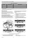
Move the s
y
stem switch on the Q674 Subbase to COOL or
AUTO. Move the cool settin
g
lever on the T874 Multista
g
e
Thermostat about 10°F
(
6°C
)
below room temperature. See
Fi
g
. 12. The coolin
g
e
q
uipment and fan should start. If the
s
y
stem has two sta
g
es of coolin
g
, both sta
g
es should start.
Move the cool lever about 10°F
(
6°C
)
above room
temperature. The coolin
g
e
q
uipment and fan should stop.
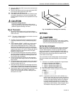
Fan
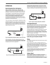
Move the s
y
stem switch to COOL, OFF, or AUTO. If
necessar
y
, position both temperature settin
g
levers so that the
heatin
g
and coolin
g
e
q
uipment are off. Move the fan switch to
ON or CONT. The fan should run continuousl
y
. When the fan
switch is in AUTO, LO, MED, or HI position, fan operation is
controlled b
y
the heatin
g
or coolin
g
s
y
stem.
Outdoor Reset Thermistor (Where
Applicable)
If the s
y
stem is supplied with a thermistor, it must be used; if
not used, thermostat performance deviates radicall
y
from
proper operation.
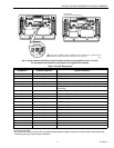
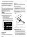
The proper thermistor operation must be verified to ensure the
correct operation of the thermostat. Check thermistor
operations as follows:
1.
Disconnect the T wire on the subbase.
2.
Use an ohmmeter to measure resistance between the
T wire and the A subbase terminal.
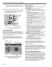
3.
Take outdoor temperature at thermistor location and find
the correct thermistor resistance on the Fi
g
. 14 chart.
4.
If the resistance measured in step 2 and the calculated
resistance in step 3 var
y
b
y
more than 15 percent, the
thermistor re
q
uires replacement. Contact Hone
y
well or
installin
g
dealer for replacement packa
g
ed outdoor ther-
mistor, part no. C815A1005.
Fig. 14. Thermistor resistance chart.
CALIBRATION
Thermostat
T874 Thermostats are accuratel
y
calibrated at the factor
y
.
They do not have provision for field calibration.
Thermometer
The thermometer in
y
our thermostat has been accuratel
y
calibrated at the factor
y
. The thermometer should onl
y
need
ad
j
ustment if it has been dropped or shifted due to mishandlin
g
.
If the setpoint lever and the thermometer readin
g
do not
a
g
ree, use the followin
g
procedure:
1.
Remove the thermostat cover b
y
pullin
g
up from the
bottom ed
g
e of the cover awa
y
from the base until it
snaps free of the cover clip.
2.
Set the thermostat cover on a table near an accurate
thermometer.
3.
Allow ten minutes for cover thermometer to sense area
temperature; compare the readin
g
s. Be careful not to
touch thermometer or breathe on it.
4.
If the readin
g
s are the same, replace cover and put the
s
y
stem into operation.
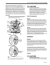
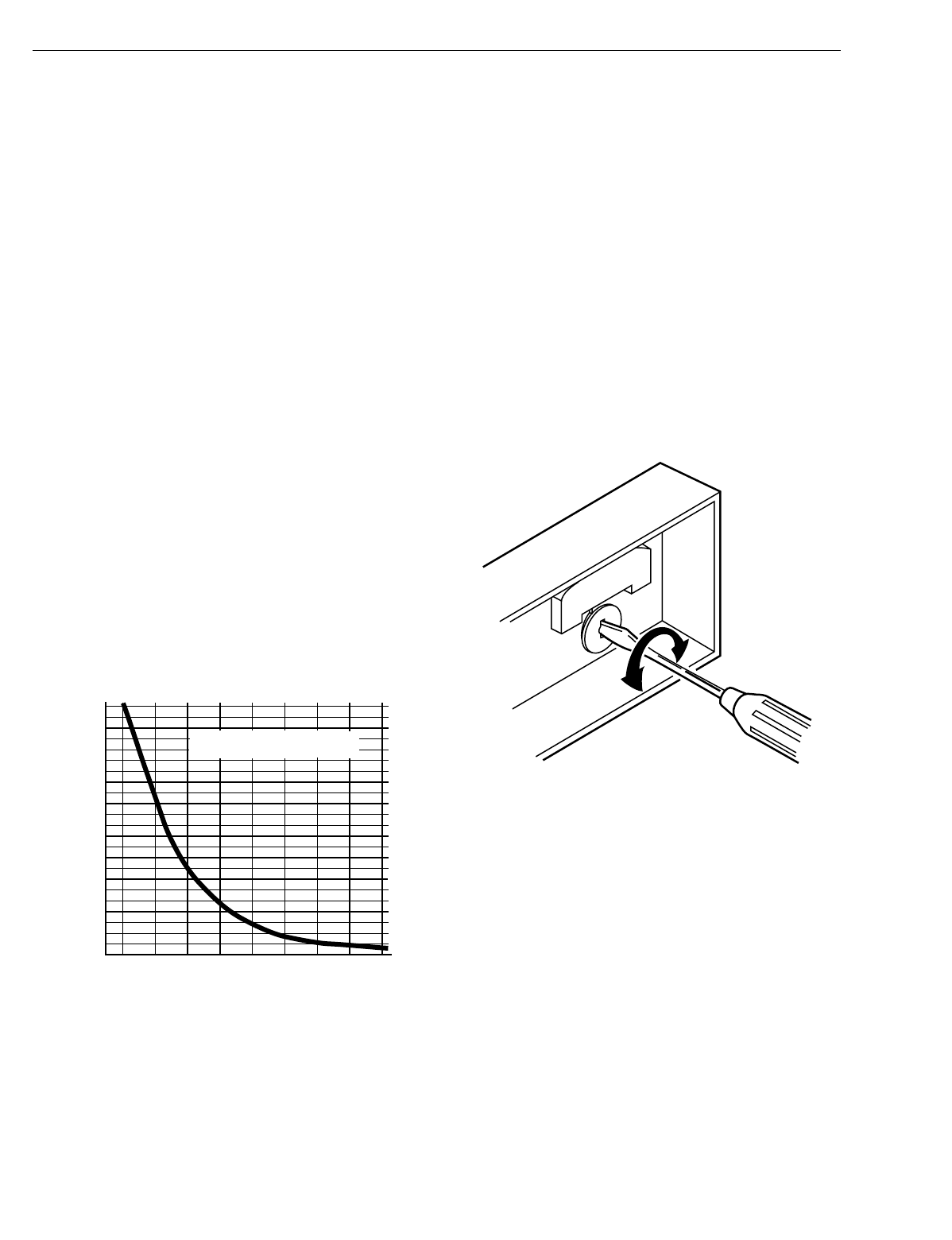
5.
If the readin
g
s are different, insert a small screwdriver in
the thermometer slot and turn it until the thermometers
have the same readin
g
. See Fi
g
. 15.
6.
Replace thermostat cover and put the s
y
stem into oper-
ation.
Fig. 15. Thermometer calibration.
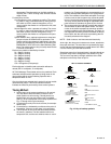
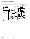
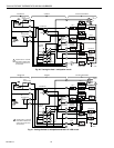
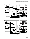
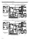
UNDERSTANDING CIRCUITS
To understand wirin
g
dia
g
rams, it is important to know what all
the s
y
mbols mean and how to trace the path of the circuits
from the transformer. See Fi
g
. 16 throu
g
h 25.
Circuit descriptions and terminolo
gy
are defined as follows:
For standard heatin
g
-coolin
g
circuits:
Auto chan
g
eover—refers to the presence of an AUTO
position in the s
y
stem switchin
g
(
EX: Q674E with OFF-
HEAT-AUTO-COOL switchin
g)
. The thermostat auto-
maticall
y
chan
g
es between heat and cool modes as
indoor temperature chan
g
es.
Manual chan
g
eover—re
q
uires a s
y
stem switch movement
to chan
g
e mode
(
EX: Q674B with HEAT-OFF-COOL
switchin
g)
. T874D Multista
g
e Thermostats with 2 heat
or 2 cool switches are shown on most standard circuits.
Most standard or TRADELINE® subbases
(
Q674A-E,G
)
can be used with T874A-F standard or TRADELINE
THERMISTOR RESISTANCE (ohms)
C815A THERMISTOR RESISTANCE
R = 400 ohms ± 10% AT 77°F (25°C)
4600
4400
4200
4000
3800
3600
3400
3200
3000
2800
2600
2400
2200
2000
1800
1600
1400
1200
1000
800
600
400
200
0
-20 0 20 40 60 80 100 120 140
TEMPERATURE OF THERMISTOR
(
°F
)
M1590A
M5070