


T874 MULTISTAGE THERMOSTATS AND Q674 SUBBASES
60-2485—826
Defrost Control
In some re
g
ions, durin
g
half or more of the heatin
g
season,
the outdoor coil operates below 32°F
(
0°C
)
Frost or ice builds
up on the outdoor coil of a heat pump similarl
y
to the frost
buildup in a household refri
g
erator. Eventuall
y
, this
accumulation of ice interferes with efficient heat transfer from
the outdoor air to the coil and refri
g
erant. Defrostin
g
is
occasionall
y
re
q
uired to remove this ice, and restore the heat
pump abilit
y
to absorb heat from the air.
Defrosting
A heat pump defrosts its outdoor coil b
y
temporaril
y
switchin
g
to the coolin
g
mode, which causes hot
g
as from the
compressor to be directed to the outdoor coil instead of to the
indoor coil so the heat pump is takin
g
heat from the home to
warm up the outdoor coil. Defrostin
g
is the
g
reatest detriment
to heat pump efficienc
y
.
Defrost Control Functions
Besides chan
g
in
g
over to the coolin
g
mode, defrostin
g
re
q
uires several more control initiated actions that follow.
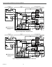
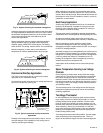
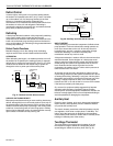
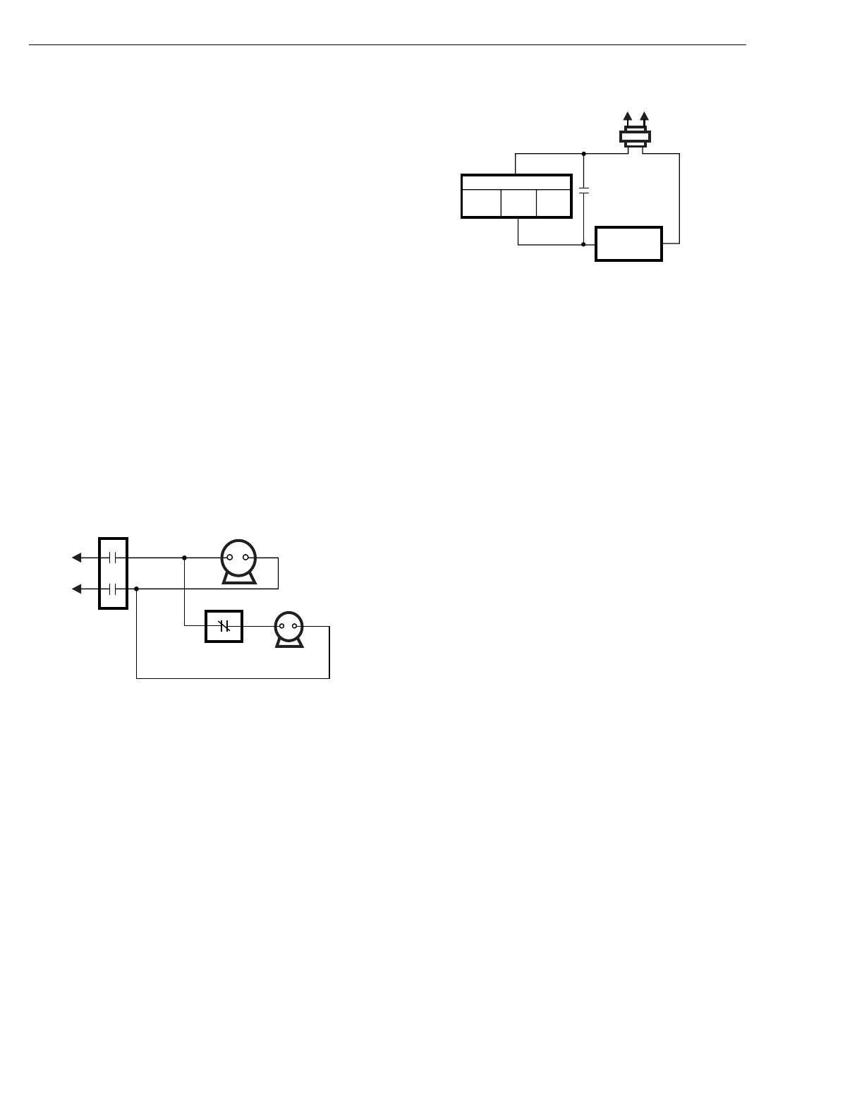
OUTDOOR FAN
When defrostin
g
has be
g
un, it is standard practice to turn off
the outdoor fan to speed up the meltin
g
process. A separate
defrost rela
y
is re
q
uired to control that fan. See Fi
g
. 37. Other
contacts can be needed on the defrost rela
y
to power the
chan
g
eover valve or power part of the auxiliar
y
heat.
Fig. 37. Outdoor fan with defrost control.
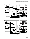
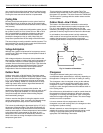
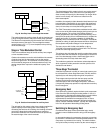
AUXILIARY HEAT DURING DEFROST
Most pump manufacturers brin
g
on some auxiliar
y
heat durin
g
defrost, althou
g
h this is not a universal practice. Some rel
y
on
the second sta
g
e of the thermostat to call for auxiliar
y
heat as
needed. Since the heat pump is operatin
g
in the coolin
g
mode
to defrost, it is deliverin
g
cold air to the livin
g
space. Auxiliar
y
heat is used to offset this coolin
g
. It re
q
uires another normall
y
open contact on the defrost rela
y
. See Fi
g
. 38.
Fig. 38. Auxiliary heat with defrost control.
WHEN TO DEFROST
Timel
y
defrostin
g
is an essential component of effective heat
pump operation. Failure to defrost often enou
g
h permits too
much ice to accumulate on the coil. At the ver
y
least, this
hurts efficienc
y
; at worst, it results in compressor dama
g
e.
Insufficient defrostin
g
is a condition the heat pump
manufacturer wants ver
y
much to avoid.
A 50 percent reduction in outdoor airflow is the maximum that
would be tolerated. So the desi
g
ner of a heat pump would
select a control point that puts the s
y
stem into defrost when
airflow throu
g
h the outdoor coil approaches half its normal
level. Restricted airflow causes a
g
reater load on the
compressor; the outdoor coil runs colder, suction pressure is
lower and the motor runs hotter.
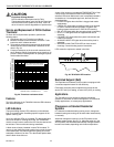
At the other end of the scale, defrostin
g
too often hurts the
overall ener
gy
efficienc
y
of the s
y
stem. Consider that in terms
of heatin
g
the buildin
g
, defrostin
g
is a bi
g
loss. Not onl
y
does
the s
y
stem stop heatin
g
, but it actuall
y
moves heat out of the
buildin
g
. If electric strip heat is used, it is a further waste
because its COP is 1.0 and not the 2.0 or more COP realized
if the heat is provided b
y
the heat pump.
So, concern for e
quipment safety
su
gg
ests fairl
y
fre
q
uent
defrostin
g
while
economy of operation
ar
g
ues for fewer
defrost c
y
cles. Since the e
q
uipment manufacturer chooses, the
balance is usuall
y
tipped in favor of more fre
q
uent defrostin
g
to
avoid the possibilit
y
of dama
g
in
g
the compressor.
Auxiliary Heat
Except in warm climates, all air-to-air heat pump installations
re
q
uire auxiliar
y
heat capabilit
y
. Electric resistance heaters
can provide this auxiliar
y
heat.
The electric heaters
(
sometimes called strip heaters
)
usuall
y
are supplied in 5 kW units or strips
(
about 17,000 Btu
)
. The
indoor unit of the heat pump is desi
g
ned to accommodate
various electric heat units so it can be used in variousl
y
sized
buildin
g
s in different parts of the countr
y
.
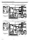
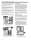
Two-Stage Thermostat
The most common heat pump control strate
gy
is for the
thermostat first sta
g
e to switch the compressor and the
second sta
g
e to switch the auxiliar
y
heat. See Fi
g
. 39.
M5839
COMPRESSOR
MOTOR
CONTACTOR
CONTROLLED BY
DEFROST RELAY
OUTDOOR
FAN MOTOR
M5835
THERMOSTAT
HEAT 2
HEAT 1
DEFROST
RELAY
CONTACT
AUXILIARY
HEAT RELAY
L1
(HOT)
L2
TRANSFORMER