


T874 MULTISTAGE THERMOSTATS AND Q674 SUBBASES
11 60-2485—8
8.
Move the HEAT and COOL levers to the maximum tem-
perature desired.
9.
Slide the stop brackets until one rests a
g
ainst the HEAT
lever and the other a
g
ainst the COOL lever.
10.
Firml
y
ti
g
hten the mountin
g
screw.
11.
If the HEAT and COOL levers are to be locked in place
at a specific temperature, use the two insulated head
screws supplied instead of the two ad
j
ustable lever stop
brackets.
CAUTION
Equipment Damage Hazard.
Do
not
use standard screws that provide metal-to-
metal contact with the stop brackets. Short circuit and
potential e
q
uipment dama
g
e can result.
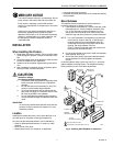
Mount Thermostat
1.
Remove the thermostat cover b
y
pullin
g
the bottom
ed
g
e of the cover awa
y
from the base until it snaps free
of the cover clip.
NOTE: The cover is hin
g
ed at the top and must be removed
b
y
pullin
g
up at the bottom.
2.
Carefull
y
remove and discard the pol
y
st
y
rene packin
g
insert that protects the mercur
y
switches durin
g
ship-
ment.
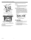
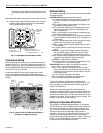
3.
If LED indication
(
EM.HT., CHECK, etc.
)
is to be used
with the Q674 Subbase, install the preprinted insert
under the thermostat setpoint scale. To install, push
both thermostat setpoint levers to the far ends of the
thermostat. Use index fin
g
er to
g
entl
y
pull out the plastic
setpoint scale about 1/4 in.
(
6 mm
)
. Position the desired
preprinted insert in the space above the LED li
g
hts.
Reposition setpoint levers.
4.
Turn over the thermostat base and note the sprin
g
fin-
g
ers that en
g
a
g
e the subbase contacts. Make sure the
sprin
g
fin
g
ers are
not
bent flat, preventin
g
proper elec-
trical contact with the subbase.
5.
Set the heat anticipator indicator
(
s
)
to the respective
current settin
g
of each sta
g
e. See Set The Heat Antici-
pator section.
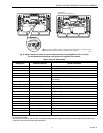
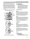
6.
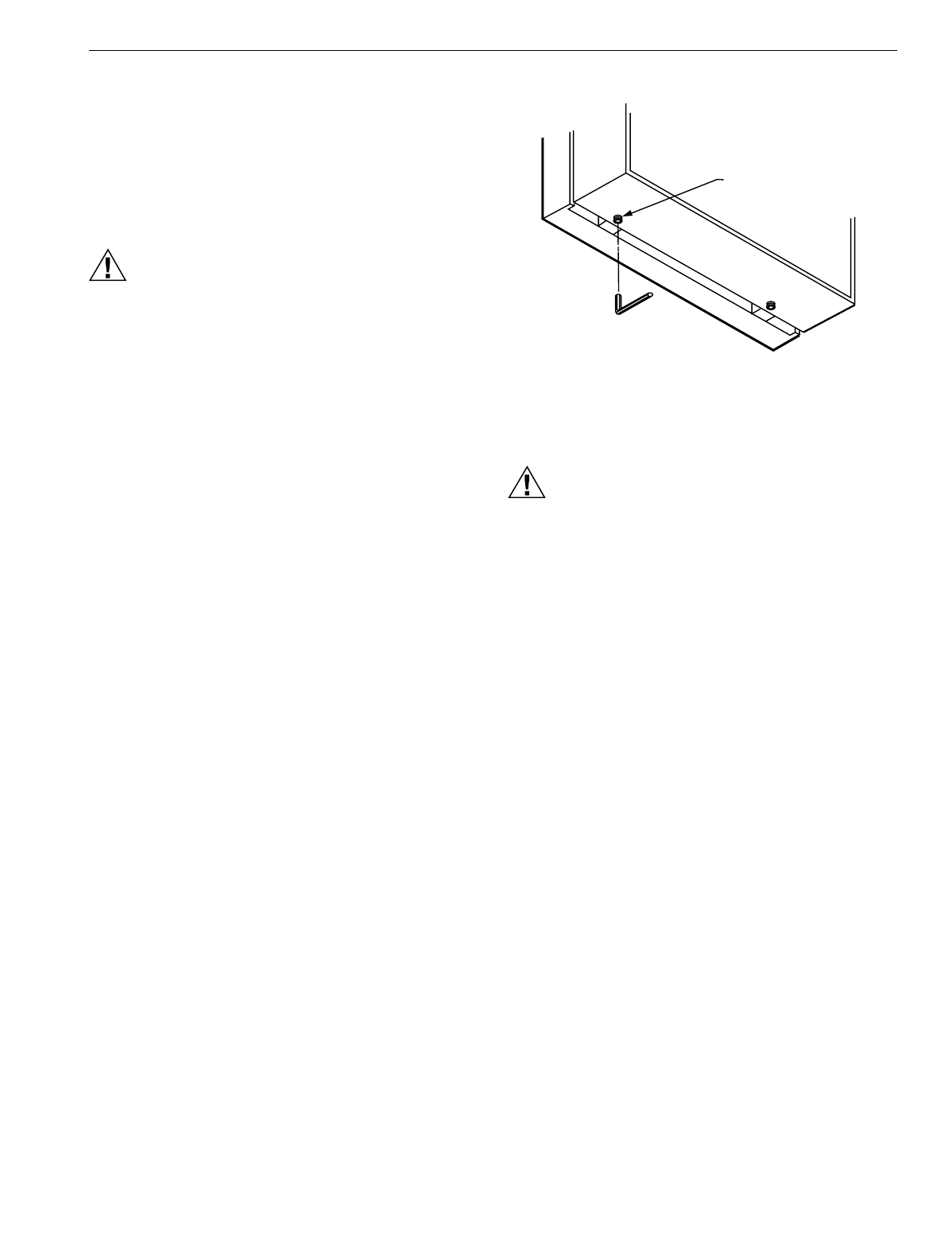
If the thermostat provides optional lockin
g
cover assem-
bl
y
, start the Allen lockin
g
screws in the cover with the
wrench provided. See Fi
g
. 10.
7.
Note the two tabs alon
g
the top inside ed
g
e of the ther-
mostat base. The tabs fit into correspondin
g
slots on top
of the subbase. Mount the thermostat on the subbase.
8.
Ali
g
n the two captive mountin
g
screws in the thermostat
base with the posts on the subbase. Ti
g
hten both
screws.
Do not overtighten screws
or dama
g
e to sub-
base posts can result.
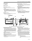
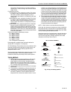
Fig. 10. Installation of locking cover assembly.
SETTINGS
CAUTION
Equipment Damage Hazard.
On s
y
stems usin
g
a
g
as valve, never appl
y
a
j
umper
across the valve coil terminals, even temporaril
y
. This
can burn out thermostat heat anticipator
(
s
)
.
Set the Heat Anticipator
Move the indicator to match the primar
y
control current draw.
When usin
g
a T874 Thermostat with two sta
g
es of heatin
g
,
set each heat anticipator to match its respective primar
y
control current draw. If
y
ou cannot find the current ratin
g
on
the primar
y
control, or if further ad
j
ustment is necessar
y
, see
NOTE and use the followin
g
procedure to determine the
current draw of each sta
g
e.
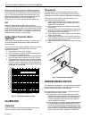
The current draw of each heatin
g
sta
g
e must be measured
with the thermostat removed and power on to the heatin
g
s
y
stem.
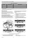
1.
Connect an ac ammeter of appropriate ran
g
e between
the heatin
g
terminals of the subbase:
a. Sta
g
e 1—between W1 and RH or R;
b. Sta
g
e 2—between W2 and RH or R
c. Sta
g
e 3—between W3 and RH or R.
2.
Move the s
y
stem switch to HEAT or AUTO.
3.
After one minute, read the ammeter and record the
readin
g
:
a. Sta
g
e 1—__________A;
b. Sta
g
e 2—__________A;
c. Sta
g
e 3—__________A.
NOTE: If e
q
uipment c
y
cles too fast, set the indicator to a
hi
g
her current ratin
g
, but not more than one-half divi-
sion at a time, and recheck the c
y
cle rate. Most con-
ventional two-sta
g
e heatin
g
e
q
uipment is desi
g
ned
to operate at three c
y
cles per hour per sta
g
e, and
one-sta
g
e heatin
g
e
q
uipment at six c
y
cles per hour,
at 50 percent load conditions. When usin
g
the T874
Thermostat in heat pump s
y
stems, set the heat
ALLEN
RETAINING
SCREWS (2)
M956