


96
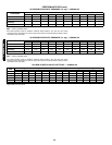
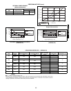
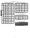
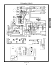
TYPICAL WIRING SCHEMATIC (cont)
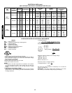
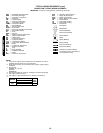
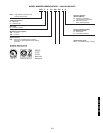
LEGEND FOR TYPICAL WIRING SCHEMATIC
IMPORTANT:
Consult unit wiring label for actual wiring schematic.
NOTES:
1. If any of the original wire furnished must be replaced, it must be
replaced with type 90 C wire or its equivalent.
2. Three phase motors are protected under primary single phasing
conditions.
3. Thermostat:
HH07AT170, 172, 174
Subbase:
HH93AZ176
4. Set heat anticipator at .8 amp for 1st stage & .3 amp for 2nd stage.
5. Use copper conductors only.
6. Use copper, copper clad aluminum. or aluminum conductors.
7.
AHA —
Adjustable Heat Anticipator
AWG —
American Wire Gage
C —
Contactor, Compressor
CAP —
Capacitor
CB —
Circuit Breaker
CC —
Cooling Compensator
CLO —
Compressor Lockout
COMP —
Compressor Motor
DB —
Defrost Board
DFT —
Defrost Thermostat
ECON —
Economizer
FPT —
Freeze-Up Protection Thermostat
FSS —
Filter Status Switch
FU —
Fuse
GND —
Ground
HC —
Heater Contactor (Strip Heat)
HPS —
High-Pressure Switch
HR —
Heater Relay
IFC —
Indoor-Fan Contactor
IFM —
Indoor-Fan Motor
LPS —
Low-Pressure Switch
LSM —
Limit Switch (Manual Reset)
MTR —
Motor
OAT —
Outdoor-Air Thermostat
OFM —
Outdoor-Fan Motor
P —
Plug
PL —
Plug Assembly
QT —
Quadruple Terminal
R —
Relay
RAT —
Return-Air Thermostat
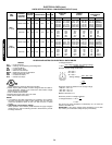
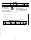
VOLTAGE
RATING
CB
MUST
TRIP
AMPS
HFG. PT. NO.
24V
POTTER & BRUNFIELD
W2BX-1024-3.2 3.2
RVS —
Reversing Valve Solenoid
SAT —
Supply Air Thermostat
SW2 —
Switch, Fully Closed
SW3 —
Switch, Minimum Vent Position
TB —
Terminal Block
TC —
Thermostat-Cooling
TH —
Thermostat-Heating
TRAN —
Transformer
Field Splice
Marked Wire
Terminal (Marked)
Terminal (Unmarked)
Terminal Block
Splice
Splice (Marked)
Factory Wiring
Field Control Wiring
Field Power Wiring
Accessory or Optional Wiring
To indicate common potential only,
not to represent wiring
50TFQ004-012
549B036-120