


14
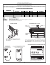
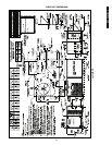
CONTROLS (cont)
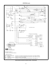
LEGEND
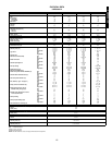
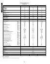
APPLICATION DATA
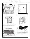
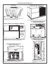
1. OUTDOOR INSTALLATION —
Units approved for outdoor
installation only.
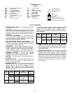
2. DUCTWORK —
Secure vertical discharge ductwork to roof
curb. For horizontal discharge applications, either attach
ductwork to unit, or use field-supplied flanges attached to
the horizontal discharge openings and attach all ductwork
to flanges.
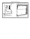
3. HORIZONTAL ECONOMI$ER —
A field-installed acces-
sory for horizontal discharge applications. Field-installed
power exhaust accessory also available for vertical or hori-
zontal EconoMi$er applications (036-120).
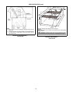
4. THRU-THE-BOTTOM POWER CONNECTIONS —
For
applications requiring thru-the-bottom connections, Bryant
accessory thru-the-bottom package must be purchased to
ensure proper connections (036-120).
5. THERMOSTAT —
Use of 2-stage heating and cooling ther-
mostat is recommended for all units. A 2-stage cooling ther-
mostat is required on units with accessory economizer to
provide integrated cooling. A two-stage thermostat is
required for all 548F/549B090,120 and 542J150,180 units.
6. HEATING-TO-COOLING —
All units are automatic
changeover from heating to cooling when automatic
changeover thermostat and subbase are used.
7. AIRFLOW —
Units are draw-thru on cooling and blow-thru
on heating.
8. MAXIMUM AIRFLOW —
To minimize the possibility of con-
densate blow-off from indoor coil, airflow through units
should not exceed 500 cfm/ton.
9. MINIMUM AIRFLOW —
For cooling, minimum airflow is
300 cfm/ton. For 548F units with electric heating, the
required minimum cfm is 900 for 548F036; 1200 for
548F048; 1500 for 548F060; 1800 for 548F072; 2250 for
548F090; 2500 for 548F102; and 3000 for 548F120, with
the following exceptions:
For 549B and 542J units with electric heating, the required
minimum cfm is 900 for 549B036; 1200 for 549B048; 1500 for
549B060; 1700 for 549B072; 2250 for 549B090; 3000 for
549B120; 3900 for 542J150; and 4500 for 542J180, with the fol-
lowing exceptions:
10. MINIMUM AMBIENT COOLING OPERATING TEMPERA-
TURE —
The minimum temperature for standard units is
25 F (036-120) and 40 F (542J150,180). With accessory
Motormaster® control, units can operate at outdoor temper-
atures down to –20 F.
11. INTERNAL UNIT DESIGN —
Due to Bryant’s internal unit
design (draw-thru over the motor), air path, and specially
designed motors, the full horsepower (maximum continuous
bhp) listed in the Physical Data table and the notes following
each Fan Performance table can be utilized with confidence.
Using Bryant motors with the values listed in the Physical
and Fan Performance Data tables
will not
result in nuisance
tripping or premature motor failure. The unit warranty will
not be affected.
AHA —
Adjustable Heat Anticipator
CB —
Circuit Breaker
CC —
Cooling Compensator
CLO —
Compressor Lockout
DAT —
Discharge Air Thermistor
DM —
Damper Motor
EAS —
Economizer Actuator
Auxiliary Switch
EMC —
Economizer Motor Contactor
FU —
Fuse
IFC —
Indoor-Fan Contactor
IFR —
Indoor-Fan Relay
L—
Light
LLS —
Liquid Line Solenoid
OAT —
Outdoor-Air Thermostat
PL —
Plug Assembly
SR —
Solenoid Relay
TB —
Ter minal Block
TC —
Thermostat Cooling
TH —
Thermostat Heating
TRAN —
Transformer
UR —
Unloader Relay
Terminal (Marked)
Terminal (Unmarked)
Terminal Block
Splice
Factory Wiring
Field Wiring
Option/Accessory Wiring
To Indicate Common Potential
Only, Not To Represent Wiring
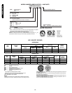
UNIT
548F
UNIT
VOLTAGE
HEATER
kW
UNIT
CONFIGURATION
REQUIRED
MINIMUM
CFM
120
208/230 42.4 Horizontal 3200
208/230 50.0 Horizontal 3200
460 50.0
Horizontal
or
Vertical
3200
090-120
575
17.0 Horizontal
or
Vertical
2800
34.0 2350
UNIT
549B
UNIT
VOLTAGE
HEATER
kW
UNIT
CONFIGURATION
REQUIRED
MINIMUM
CFM
120
208/230 50.0
Horizontal
or
Vertical
3250
460 50.0
Horizontal
or
Vertical
3400