


2
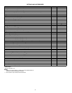
TABLE OF CONTENTS
Page
Features/Benefits . . . . . . . . . . . . . . . . . . . . . . . . . . . . . . . . . 1-3
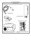
Options and Accessories . . . . . . . . . . . . . . . . . . . . . . . . . . . 4-9
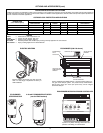
Controls. . . . . . . . . . . . . . . . . . . . . . . . . . . . . . . . . . . . . . . 10-14
Application Data . . . . . . . . . . . . . . . . . . . . . . . . . . . . . . . . 14,15
Typical Piping and Wiring . . . . . . . . . . . . . . . . . . . . . . . . . 16,17
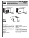
548F036-120
Model Number Nomenclature . . . . . . . . . . . . . . . . . . . . . . . . .18
ARI Capacity Ratings . . . . . . . . . . . . . . . . . . . . . . . . . . . . . . .18
Physical Data . . . . . . . . . . . . . . . . . . . . . . . . . . . . . . . . . . 19,20
Base Unit Dimensions. . . . . . . . . . . . . . . . . . . . . . . . . . . . 21,22
Accessory Dimensions . . . . . . . . . . . . . . . . . . . . . . . . . . . 23,24
Selection Procedure . . . . . . . . . . . . . . . . . . . . . . . . . . . . . . . .25
Performance Data . . . . . . . . . . . . . . . . . . . . . . . . . . . . . . . 26-55
Electrical Data. . . . . . . . . . . . . . . . . . . . . . . . . . . . . . . . . . 56-64
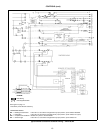
Typical Wiring Schematic . . . . . . . . . . . . . . . . . . . . . . . . . 65,66
549B036-120
Model Number Nomenclature . . . . . . . . . . . . . . . . . . . . . . . . .67
ARI Capacity Ratings . . . . . . . . . . . . . . . . . . . . . . . . . . . . . . .67
Physical Data . . . . . . . . . . . . . . . . . . . . . . . . . . . . . . . . . . 68,69
Base Unit Dimensions. . . . . . . . . . . . . . . . . . . . . . . . . . . . 70,71
Accessory Dimensions . . . . . . . . . . . . . . . . . . . . . . . . . . . 72,73
Selection Procedure . . . . . . . . . . . . . . . . . . . . . . . . . . . . . . . .74
Performance Data . . . . . . . . . . . . . . . . . . . . . . . . . . . . . . . 75-90
Electrical Data. . . . . . . . . . . . . . . . . . . . . . . . . . . . . . . . . . 91-94
Typical Wiring Schematic . . . . . . . . . . . . . . . . . . . . . . . . . 95,96
Guide Specifications — 548F and 549B036-120 Units . . 97-100
542J150,180
Model Number Nomenclature . . . . . . . . . . . . . . . . . . . . . . . .101
ARI Capacity Ratings . . . . . . . . . . . . . . . . . . . . . . . . . . . . . .102
Physical Data . . . . . . . . . . . . . . . . . . . . . . . . . . . . . . . . 102,103
Base Unit Dimensions. . . . . . . . . . . . . . . . . . . . . . . . . . . . . .104
Accessory Dimensions . . . . . . . . . . . . . . . . . . . . . . . . . 105-107
Selection Procedure . . . . . . . . . . . . . . . . . . . . . . . . . . . . . . .108
Performance Data . . . . . . . . . . . . . . . . . . . . . . . . . . . . . 109-114
Electrical Data. . . . . . . . . . . . . . . . . . . . . . . . . . . . . . . . . . . .114
Typical Wiring Schematic . . . . . . . . . . . . . . . . . . . . . . . 115-117
Guide Specifications — 542J150,180 . . . . . . . . . . . . . 118-121
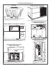
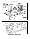
DURABLE, DEPENDABLE CONSTRUCTION —
Designed for
durability in any climate, the weather-resistant cabinets are con-
structed of galvanized steel and bonderized, and all exterior
panels are coated with a prepainted baked enamel finish. The
paint finish is non-chalking, and is capable of withstanding
ASTM B117 500-hour Salt Spray Test. All internal cabinet pan-
els are primed, permitting longer life and a more attractive
appearance for the entire unit.
In addition, all size 036-120 units are designed with a single,
continuous top piece to eliminate any possible leaks. Totally
enclosed condenser-fan motors and permanently lubricated
bearings provide additional unit dependability.
Patented State-of-the-Art Chronotemp™ Defrost System
uses time and temperature to keep the outdoor coil frost-free for
economical, dependable operation. The Chronotemp defrost
board can be easily configured for defrost cycles every 30, 50, or
90 minutes.
Dependable 4-Way Valve Operation
safely and efficiently
accomplishes cycle reversals, defrost, and normal operation.
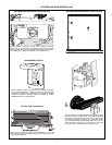
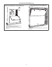
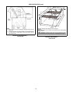
EASY INSTALLATION AND CONVERSION
All Units are Shipped in the Vertical Duct Configuration
for
fit-up to standard roof curbs. (3 different curb sizes fit unit sizes
036-072, 090-120, 150 and 180 respectively.) The contractor
can order and install the roof curb early in the construction
stage, before decisions on size requirements are made.
All units feature a base rail design with forklift slots and rigging
holes for easier maneuvering. Durable packaging protects all
units during shipment and storage.
The units can be easily converted from a vertical to a horizontal
duct configuration by relocating the panels supplied with the
unit.
To Convert 036-120 Units
from vertical to horizontal discharge,
simply relocate 2 panels. The same basic unit can be used for
a variety of applications and can be quickly modified at the
jobsite.
To Convert 150,180 Units
from vertical to horizontal discharge,
use the optional horizontal supply/return adapter roof curb.
Convenient Duct Openings
in the unit basepans permit side-
by-side or concentric duct connections (see Application Data
section) without requiring internal unit modification (150,180
only).
NOTE:
On units using horizontal supply and return, the acces-
sory barometric relief or power exhaust MUST be installed on
the return ductwork.
Thru-the-bottom service connection capability comes standard
with the rooftop unit to allow power and control wiring to be
routed through the unit’s basepan, thereby minimizing roof pen-
etrations (to prevent water leaks). Power and control connec-
tions are made on the same side of the unit to simplify
installation.
The Non-Corrosive Sloped Condensate Drain Pan
permits
either an external horizontal side condensate drain (outside the
roof curb) or an internal vertical bottom drain (inside the roof
curb). Both options require an external, field-supplied P-trap.
Standard 2-in. Throwaway Filters
are easily accessed
through a removable panel located above the air intake hood.
No tools are required to change unit filters.
All 036-120 Units are Designed with a Single, Continuous
Top Piece
to eliminate leaking at the seams or gasketing.
Belt-Driven Indoor-Fan Motors
allow maximum on-site flexibil-
ity without changing motors or drives.
Field-Installed Accessory Electric
heaters are available in a
wide range of capacities. An available single-point wiring kit
makes installation simple.
Low Voltage Wiring Connections
are easily made due to the
large terminal board which is located for quick, convenient
access.
In addition, color-coded wires permit easy tracing and
diagnostics.
PROVEN COMPRESSOR RELIABILITY
Design techniques feature computer-programmed balance
between compressor, condenser, and evaporator. Bryant-
specified hermetic compressors are equipped with compressor
overcurrent and overtemperature protection to ensure
dependability.
All units have a fixed-orifice (036-120) or TXV metering
device (150,180) which precisely controls refrigerant flow, pre-
venting slugging and flood-back, while maintaining optimum unit
performance. Refrigerant filter driers are standard.
Standard Low Ambient Cooling Operation to 25 F (036-120)
or 40 F (150,180);
optional head pressure control kit available
for outdoor ambient conditions to –20 F.