


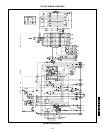

120
GUIDE SPECIFICATIONS — 542J150,180 UNITS (cont)
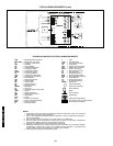
K. Electrical Requirements:
All unit power wiring shall enter unit cabinet at a single
factory-predrilled location.
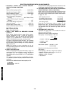
L. Motors:
1. Compressor motors shall be cooled by refrigerant
gas passing through motor windings and shall have
line break thermal and current overload protection.
2. Indoor-fan motor shall have permanently lubricated
bearings and inherent automatic-reset thermal over-
load protection.
3. Totally enclosed outdoor-fan motor shall have perma-
nently lubricated bearings, and inherent automatic-
reset thermal overload protection.
M. Special Features:
Certain features are not applicable when the features
designated * are specified. For assistance in amending
the specifications, contact your local Bryant Sales Office.
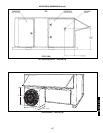
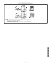
1. Roof Curbs (Horizontal and Vertical):
a. Formed galvanized steel with wood nailer strip
and shall be capable of supporting entire unit
weight.
b. Permits installation and securing of ductwork to
curb prior to mounting unit on the curb.
2. Horizontal Adapter Roof Curb:
Includes factory-assembled adapter and duct which
substantially improves indoor fan static motor perfor-
mance (static regain).
NOTE:
Power exhaust and barometric relief must be
mounted in the return ductwork when used in con-
junction with this accessory.
*3. Integrated EconoMi$er:
a. Integrated integral modulating type capable of
simultaneous EconoMi$er and compressor
operation.
b. Includes all hardware and controls to provide
cooling with outdoor air.
c. Equipped with low-leakage dampers, not
to exceed 2% leakage at 1 in. wg pressure
differential.
d. Capable of introducing up to 100% outdoor air.
e. EconoMi$er shall be equipped with a barometric
relief damper.
f. Designed to close damper(s) during loss-of-
power situations with spring return built into
motor.
g. Dry bulb outdoor-air temperature sensor shall be
provided as standard. Enthalpy, differential tem-
perature, and differential enthalpy control shall be
provided as an option.
h. EconoMi$er is a gear-driven parallel blade
design.
i. EconoMi$er shall provide control of internal build-
ing pressure through its accessory two-stage
power exhaust function.
j. EconoMi$er shall be capable of control from a 4
to 20 mA signal.
4. Barometric Relief Damper:
a. Package shall include damper, seals, hardware,
and hoods to relieve excess internal pressure.
b. Damper shall close due to gravity upon unit
shutdown.
5. Manual Outdoor-Air Damper:
Manual damper package shall consist of damper,
birdscreen, and rainhood which can be preset
to admit up to 50% outdoor air for year round
ventilation.
*6. 25% Two-Position Damper:
a. Two-position damper package shall include single
blade damper and motor. Admits up to 25% out-
door air.
b. Damper shall close upon indoor fan shutoff.
*7. Head Pressure Control Package:
Consists of solid-state control and condenser-coil
temperature sensor to maintain condensing temper-
ature between 90 F and 110 F at outdoor ambient
temperatures down to –20 F by condenser-fan speed
modulation or condenser-fan cycling and wind
baffles.
*8. Electric Resistance Heaters:
a. Open wire nichrome elements with all necessary
safety operating controls.
b. UL listed and indicated on basic unit information
plate.
c. Available in multiples to match heating requirements.
d. Single point kits available for each heater when
required.
*9. Electronic Programmable Thermostat:
Capable of using deluxe full-featured electronic ther-
mostat. Shall use built-in compressor cycle delay
control for both heating and cooling duty.
*10. Thermostat and Subbase:
Provides staged cooling and heating automatic (or
manual) changeover, fan control, and indicator light.
*11. Unit-Mounted, Non-Fused Disconnect Switch:
Shall be factory-installed, internally mounted. NEC
and UL approved non-fused switch shall provide unit
power shutoff. Shall be accessible from outside the
unit and shall provide power off lockout capability.
*12. Convenience Outlet:
Shall be factory-installed and internally mounted with
easily accessible 115-v female receptacle. Shall
include 15 amp GFI receptacle with independent
fuse protection. Voltage required to operate conve-
nience outlet shall be provided by a factory-installed
step-down transformer. Shall be accessible from out-
side the unit.
*13. Compressor Cycle Delay:
Unit shall be prevented from restarting for minimum
of 5 min. after shutdown.
*14. Fan/Filter Status Switch:
Provides status of indoor (evaporator) fan (ON/OFF)
or filter (CLEAN/DIRTY). Status shall be displayed
over communication bus when used with direct digital
controls or with an indicator light at the thermostat.
50TFQ004-012
542J150,180