


Brute Mini Hydronic Boiler
Page 5
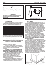
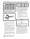
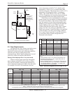
2.2 Field Assembly
1. Brute Mini boilers have built-in draft diverter for
natural draft operation.
2. Find the vent damper box which is located in the
boiler package.
3. Install the vent damper directly to the top of the
draft diverter outlet with the damper operator
facing to the front of the boiler, and with the flow
direction arrow pointing upward. Use the vent
damper wire harness provided with the boiler to
connect the vent damper to the boiler. The
bracket end of the harness should be connected
to the vent damper actuator.
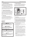
4. For Model BJVS only: Install the metal plug
provided with the vent damper onto the damper
plate hole. Disregard the metal plug in case of
standing (continuous) pilot boilers. For all
BJVT models, the damper plate hole should
never be blocked.
5. Do not modify the automatic vent damper
device. It is very important that no other vents
are closed. Provide at least six inches clearance
between the automatic vent damper and
combustible construction, and be sure to allow
access for servicing the damper.
6. Install the temperature/pressure gauge provided
in the parts box.
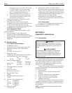
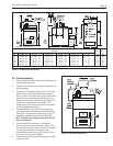
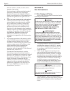
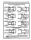
Figure 1. Dimensional Information.
Dimensions in inches cm
Dimensions
Water Gas
inches cm
Conn. Conn.
Size* A B C D E V
in. in.
50 13-3/8 34 27-3/4 71 23-5/8 60 21-3/4 55 26-1/2 67 4 10 1-1/4 1/2
75 13-3/8 34 27-3/4 71 24-1/8 61 21-3/4 55 27-1/2 70 5 13 1-1/4 1/2
100 16-7/8 43 28-3/4 73 24-1/8 61 22-3/4 58 27-1/2 70 5 13 1-1/4 1/2
125 16-7/8 43 28-3/4 73 23-5/8 60 22-3/4 58 27-1/2 70 6 15 1-1/4 1/2
160 20-3/8 52 28-3/4 73 23-5/8 60 22-3/4 58 27-1/2 70 6 15 1-1/4 1/2
225 25-5/8 65 31-1/2 80 23-1/4 59 23-3/4 63 27-1/2 70 7 18 1-1/4 *3/4**
* Values shown are for both BJVS and BJVT Models **1/2 for propane
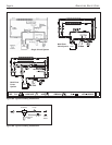
Figure 2. Field Assembly Items.