


BRADFORD WHITE CORP.
Page 26
1. Lubricate the water circulating pump per the
instructions on the pump.
2. If a strainer is employed in a pressure reducing
valve or the piping, clean it every six months.
3. At start-up, and periodically thereafter, the
burner flame should be observed. If the flame
has the appearance of ‘sooting’ tips, check for
debris near the orifices and call the service
technician.
4. Inspect the venting system for obstruction,
leakage or corrosion at least once a year.
5. Do not store or use gasoline or other flammable
vapors, liquids or chemicals in the vicinity of
this or any other appliance.
Ne pas entreposer ni utiliser d’essence ni
d’autres vapeurs ou liquides inflammables à
proximité de cet appareil ou de tout autre
appareil.
6. Do not use this boiler if any part has been under
water. Immediately call a qualified service
technician to inspect the heater and replace any
part of the control system and any gas control
which has been under water.
N’utilisez pas cet appareil s’il a été plongé dans
l’eau, même partiellement. Faites inspecter
l’appareil par un technicien qualifié et remplac
ez toute partie du système de contrôle et toute
commande qui ont été plongés dans l’eau.
7. Be sure that all combustion air and ventilation
openings are unobstructed.
8. Upon completion of the installation, inspect the
external surfaces of the heat exchanger for
fouling based on the following schedule:
24 hours 7 days 30 days 90 days
Once every six months thereafter.
9. If the boiler is not going to be used for long
periods of time in locations where freezing
occurs, it should be completely drained of all
water. To accomplish this, there is a drain valve
on the right side of the boiler which can be
opened. This will drain the right side of the
boiler. There are two plugs located on the left
side of the heater which must be removed to
drain that side. Both sides must be drained.
10. The gas and electric controls on the boiler are
engineered for long life and dependable
operation, but the safety of the equipment
depends on their proper functioning. It is
strongly recommended that the basic items listed
below be inspected by a qualified service
technician every year.
a. Water temperature controls
b. Pilot safety system.
c. Automatic gas valves.
d. Flow sensing safety devices.
e. Vent dampers and power venters.
f. Venting system.
NOTE: The Warranty does not cover damage caused
by lack of required maintenance, lack of water flow, or
improper operating practices.
12. Fouling on the external surfaces of the heat
exchanger is caused by incomplete combustion,
and is a sign of venting and/or combustion air
problems. The heat exchanger can be inspected
by using a flashlight and placing a mirror under
the burners. An alternate method is to remove the
venting and top panel to inspect the exchanger
from above. The vent system should be
inspected at the same time. If cleaning is
required:
a. Shut off all power to the boiler.
b. Remove the draft hood, venting top, flue
collector, and heat exchanger baffles.
c. Remove the burners by lifting them off the
orifices and pulling them out of the boiler.
d. Use a hand-operated spray bottle filled with
water, and a wire brush to clean soot and
loose scale from the underside of the heat
exchanger. DO NOT USE COMPRESSED
AIR, HIGH PRESSURE WATER OR A
GARDEN HOSE.
e. Clean any fallen debris from the bottom of
the unit.
f. Check to make sure the burner ports and
pilot assembly are free of debris before
returning the burners to their original
position.
g. Reassemble the boiler in reverse order,
making sure to replace the heat exchanger
baffles.
8.2 Boiler Components and Their
Operation
1. Gas Valve / Regulator - The gas valve controls
gas flow into the manifold. It provides flow only
when the temperature control requires heat and
only if all safety controls enable operation. It is
also a positive pressure regulator. It regulates the
gas pressure in the manifold to specifications
addressed earlier in this manual. This is
necessary for proper operation of the burner
system. BJVS 100-225 Only - Gas Valve /
Regulator has two output stages controlled by
two-stage temperature control.
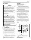
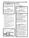
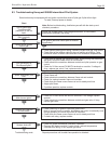
Figure 14. 1) BJVS Pilot; 2) BJVH Pilot;
3) Main Burner Flame Pattern; 4) BJVT Pilot.