


BRADFORD WHITE CORP.
Page 12
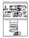
A full sized, 1¼" bypass with balancing valves is
strongly recommended for all systems, and required
when: 1) the boiler is installed without primary-
secondary piping in a multiple zone system; 2) when
the return water temperature can be expected to be
lower than 120°F (44°C); or 3) whenever the system
piping on the outlet side of the boiler may allow
reduced flow through the heat exchanger, causing
excessive temperature rise (see Section 5.2).
Note: Bradford White strongly recommends a
primary/secondary piping system for all installations,
especially sizes 125, 160 and 225. In this system, a
circulator is dedicated to pumping the boiler only. This
circulator should be sized for the boiler head loss and
flow rate.
All precautions must be taken by the installer to
insure that a maximum temperature rise through the
boiler does not exceed 30°F (17°C). The temperature
rise on boilers installed in multi-zone systems using
zone valves must be taken when the zone of the
longest length and/or the zone of the highest head loss
is open.
A full size, 1¼" diameter by-pass with
balancing valve must be installed if a return water
temperature below 120°F (44°C) is expected under
operating conditions regardless of boiler size. This
may be expected in many systems, including in-
floor radiant and snow melt systems.
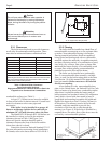
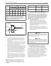
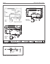
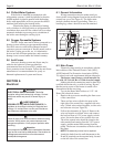
Adjusting the bypass:
Refer to figure 7. Provide a means of measuring
temperature on the inlet pipe to the boiler such as
using a strap on or infrared themometer. Starting with
both balancing valves fully open, start the boiler.
Adjust the balancing valve on the return to the system
slowly to provide 120°F (44°C) water at the inlet to
the boiler, leaving the bypass balancing valve fully
open. As the system warms up, this valve may need to
be adjusted open. In rare cases, this valve will have to
be kept fully open, and the bypass balancing valve
adjusted toward closed to prevent heated bypass water
from satisfying the call for heat when the system is up
to temperature.
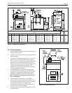
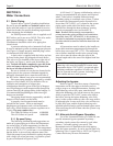
5.2 Alternate Auto-Bypass Operation
Use of the themostatic union, p/n 2400-030, can
provide automatic bypass operation in primary -
secondary piped systems (but cannot be used when
primary - secondary piping is not used). The
thermostatic union is installed on the outlet piping,
after the bypass assembly. It can be used in place of a
balancing valve. It opens fully at 140°F (see Figure 6).
Contact the factory for more information.
SECTION 5.
Water Connections
5.1 Water Piping
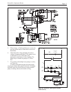
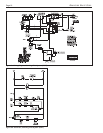
Figure 6 shows ‘typical’ plumbing installations.
Be sure to provide unions and isolation valves at the
boiler inlet and outlet so it can be isolated for service.
Check local codes for specific plumbing requirements
before beginning the installation.
An ASME pressure relief valve is supplied on all
BJV boilers, and is pre-set at 30 PSI. The valve outlet
piping must discharge to a drain. Under no
circumstances should the relief valve piping be a
closed circuit.
A pressure reducing valve (automatic feed) must
be used to maintain system at constant proper pressure
(see Figure 6). Supply properly installed purge valves
to eliminate air from each circuit.
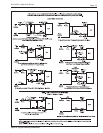
A drain valve is supplied with the boiler, and can
be found in the plastic bag shipped with each boiler.
This valve is to be installed on the lower right side of
the boiler, see Figure 1, and is used for draining the
unit. To drain the boiler completely, open the drain
valve and remove the two drain plugs located on
the lower left side of the boiler.
Be sure to include air vent devices located at the
highest point in the system to eliminate trapped air,
and an air elimination device near the outlet side of
the BJV boiler. Manual vent valves are recommended.
Hot water piping should be supported by suitable
hangers or floor stands, NOT by the boiler. Due to
expansion and contraction of copper pipe,
consideration should be given to the type of hangers
used. Rigid hangers could transmit noise through the
system caused by the piping sliding in the hangers. It
is recommended that padding be used when rigid
hangers are installed.
Gas piping should also be supported by suitable
hangers or floor stands, not the boiler.
A properly sized expansion tank must be
included in the system. offers an aircharged
diaphragm-type expansion tank, with an automatic
feed valve, which includes a pressure regulator set at
12 psig. The part numbers are:
Less Than 20 Gallons in System A0066800
20 to 45 Gallons in System A0066900
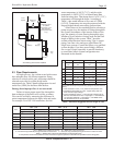
5.1.1 By-pass Piping
The following information and suggestions are
made on by-pass piping as it affects the temperature
rise at the boiler. A boiler temperature rise must be
taken on all BJV boiler installations. If the temperature
rise exceeds 30°F (17°C) at full rate, it is an indication
that the boiler is not receiving adequate water flow.
Check the pump for any obstruction, replace the pump
with a larger size where necessary, or install a system
by-pass as indicated in Figures 6 and 7.