


BRADFORD WHITE CORP.
Page 30
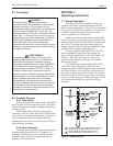
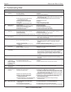
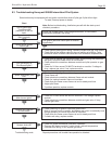
9.4 Electrical Troubleshooting
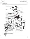
1. Remove the control box cover on the front of the
boiler.
2. Verify that 115V is reaching the boiler by testing
across the black wire on the pump relay and the
white wire on the transformer.
3. Verify 24V transformer output by placing the
meter leads on the yellow and red wires. If 24V
is not evident, replace the transformer. Perform
the following series of tests with one meter lead
attached to the yellow wire on the transformer.
4. Place the second lead on the "W" connection on
the terminal board. Turn the wall thermostat high
enough to call for heat. If the meter fails to
register 24V, the thermostat or its circuit may be
defective.
5. Make sure thermostat is set high enough to call
for heat. Place second lead on the "A"
connection on the terminal board. If voltage is
evident, skip to step 6. If no voltage, test the
circuit between the red wire on the transformer
and terminal 4 on the pump relay; from terminal
6 on the pump relay and the "A" connection on
the terminal board; and from the purple wire
terminal on the pump relay to the "W"
connection on the terminal board. If no output is
found, the
connections or the pump relay could be defective.
6. Place the second lead on the orange wire
terminal on the hi-limit switch. If no voltage
across the switch, check for defective hi-limit,
open circuit due to excessive water temperature,
or a low temperature setting.
7. Place the second lead on the orange wire
terminal on the blocked vent safety switch. If
voltage is present, the vent damper is open. If
voltage isn't present, connections or the vent
damper could be defective.
8. Verify the voltage across the blocked vent and
roll-out safety switches.
9. On BJVT boilers, test for voltage at the "TH"
terminal on the gas valve. If none is found,
follow steps 1 through 8.
10. If it is determined that there is voltage to the gas
valve, the pilot is lit and the thermocouple is
properly positioned, and the thermostat is set
high enough to call for heat, the gas valve or the
pilot thermocouple may be defective
11. There are two tests necessary to make sure the
problem is not in the pilot thermocouple. The
first test can be performed by unscrewing the
compression fitting on the gas valve, and placing
one millivoltmeter lead on the center post of the
tube and the other lead on the copper tubing. If
the meter shows a reading of approximately 30
millivolts, proceed to the second test. If it
doesn't, replace the pilot thermocouple. The
second test requires the use of a Millivolt
Reading Adapter to test the thermocouple under
load. Once again, remove the pilot thermocouple
compression fitting from the gas valve. Replace
it with a Millivolt Reading Adapter, and screw
the thermocouple fitting into the end of the
adapter. Attach one lead from the millivoltmeter
to either side of the adapter and the other lead to
ground. Light the pilot and set the wall
thermostat high enough to call for heat. With the
boiler firing, take a millivolt reading. It should
be in the 15 millivolt range. If it isn't, replace the
pilot thermocouple.
Caution
Label all wires prior to disconnection when servicing
controls. Wiring errors can cause improper and
dangerous operation. Verify proper operation after
servicing.
ATTENTION
Au moment de l’entretien des commandes, mettez
des étiquettes sur tous les fils avant de les
débrancher. Des erreurs de câblage peuvent
causer un fonctionnement inadéquat et dangereux.
Vérifier que tout fonctionne bien après votre
entretien.
SECTION 10.
Glossary
10.1 Glossary of Terms
Air Vent
Another device used to purge air from the circuit.
Should be located at the highest point in the circuit.
Branch
The section(s) of supply and return piping, including
the heat distribution units (see below), connected
directly to the trunk. Also referred to as a "zone."
By-pass
A section of pipe (including an adjustable valve) that
diverts part of the water flow from the boiler outlet to
the inlet, adjusted to maintain minimum flow
requirement (GPM) or inlet water temperature.
Circuit
Entire water circulation piping, beginning and ending
at the boiler (Series Loop System).
Expansion Tank (Compression Tank)
Installed in the circuit to accommodate excess water
produced by heat expansion, and to maintain the
system pressure.