


BRADFORD WHITE CORP.
Page 16
5.4 Chilled Water Systems
If the boiler is installed in conjunction with
refrigeration systems, it shall be installed so that the
chilled medium is piped in parallel with the heating
boiler with appropriate valves to prevent the chilled
medium from entering the heating boiler.
When boiler piping is connected to heating
coils, which are in close proximity to refrigerated air
circulation, there must be flow control valves or other
automatic methods to prevent gravity circulation of
the boiler water during the cooling cycle.
5.5 Oxygen Permeable Systems
The BJV boiler must not be direct connected to a
heating system utilizing oxygen permeable tubing.
Provide a water-to-water heat exchanger between
systems to prevent corrosion of ferrous metals such as
the boiler’s piping wet walls, etc. Air elimination
devices are not sufficient protection, and corrosion
damage is not covered under the limited warranty.
5.6 Anti-Freeze
Non-toxic heating system anti-freeze may be
added to the hydronic system provided the
concentration does not exceed 50%, and the anti-
freeze contains an anti foamant. Follow the anti-freeze
manufacturer’s recommendations for yearly or
biannual replacement of system anti-freeze.
SECTION 6.
Electrical
WARNING
ELECTRICAL SHOCK HAZARD. This boiler
contains wiring that carries high voltage. Contact
with these wires may result in severe injury or
death.
AVERTISSEMENT
POSSIBILITÉ DE CHOCS ÉLECTRIQUES. Ce
système de chauffage contient du filage de haut
voltage. Un contact avec ces fils peut résulter en
des blessures sérieuses ou la mort.
Caution
Label all wires prior to disconnection when servicing
controls. Wiring errors can cause improper and
dangerous operation. Verify proper operation after
servicing.
Attention
Au moment de l’entretien des commandes, étiquetez
tous les fils avant de les débrancher. Des erreurs de
câblage peuvent entraîner un fonctionnement
inadéquat et dangereux.
6.1 General Information
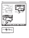
Wiring connections must be made exactly as
shown in the wiring diagram found on the inside of the
control box cover (see Figure 8). The boiler must
include a definite means of grounding. There is a
bonding lug, where a bond wire must be attached.
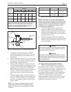
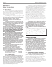
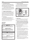
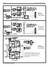
Figure 8. Field Wiring Connections.
Transformer BLK
BLK - Hot
WHT - Neutral
WHT - Neutral
BRN - Hot
On = Call
for heat
Power
Supply
115VAC
60 Hz
To Pump
115VAC
3/4 H.P.
Max
BRN WHT
Pump Relay
115V Field Wiring
115V Factory Wiring
GRN - Ground
6.2 Main Power
Electrical wiring must be in accordance with the
latest edition of the National Electric Code (NEC),
ANSI/National Fire Protection Association (NFPA)
70, unless local code requirements indicate otherwise.
The heater comes factory-wired intended for
use with 115 Volt, 60 Hz AC field electrical supply.
Making electrical connections must be done by a
certified electrician only, as with all wiring. Be sure
that the power source to the heater is turned off or
disconnected before servicing.
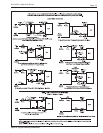
To wire the Brute Mini boiler to a 115V / 60
Hertz (Hz) electrical source:
1. Remove the two screws attaching the front cover
of the control box.
2. There are four wires coiled in the area on the
right side of the control box, supplied with wire
nuts: 2 black wires twisted together, a white wire
and a brown wire (see Figure 8).
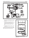
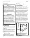
3. Follow the schematics in Figure 9. Remove the
wire nut from the two black wires, and connect
the hot lead from a 115V power supply to both
wires. Secure the three wires with the wire nut.
The white, neutral wire should be joined to the
other neutral lead coming from the 115V power
supply, and the neutral lead coming from the
pump. The brown wire attaches to the hot side of
the pump.
NOTE: No external junction box is required.
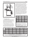
4. Attach the leads from the wall thermostat to the
R and W terminals on the terminal strip, located
on the left side of the control box.