


Brute Mini Hydronic Boiler
Page 15
5.3 Flow Requirements
All high recovery, low volume water boilers must
have adequate flow for efficient operation. Pump
selection is critical to this goal, and pumps should be
selected to provide for system design water
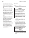
temperature rise. Table 6 details temperature rise and
water flow (GPM) for the Brute Mini boilers.
Damage from improper flow is not warranted.
Failure to insure proper water flow through the
heat exchanger of the boiler will void the warranty.
Flow can be verified by measuring the difference in
water temperatures between the boiler inlet and outlet.
For example: For a BJV-100 installation, the inlet
water temperature is 160°F (71°C), and the outlet
temperature is 180°F (82°C) at Normal Input Rate
from the rating plate. That means there is a 20° (11°C)
temperature rise through the boiler. According to
Table 1, that would indicate a flow rate of 8 GPM
(0.5L/S). Temperature rise must be measured with the
longest (highest head) zone calling for heat alone.
Other factors to be considered before selecting a
pump are pipe size, the number of fittings throughout
the system, smoothness of the interior surface of the
pipe, the quantity of water flowing through the pipe,
whether a glycol solution is being used, and the total
length of piping in the system. Table 7 provides
examle pump selection criteria using Type L copper
piping, one zone valve and up to eight elbows for
single zone systems. Consult the factory or a qualified
system designer if you have more fittings, different
size or type of pipe (especially in retrofit situations),
or some other unique system configuraiton not
illustrated in this manual.
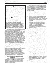
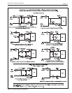
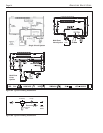
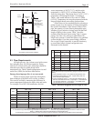
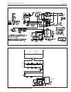
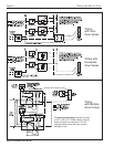
Figure 7. By-pass Piping.
Balancing Valve
or optional
thermostatic union,
P/N 2400-030.
(Primary/Secondary
only)
To
System
From
System
In
(Return)
Out
(Supply)
Drip
Leg
Left Side View
A full size by-pass must be installed.
*A circulator and/or primary/secondary piping are required. Consult
factory.
1. Chart is based on 30°F (17°C) maximum temperature rise.
2. Calculations are based on Type L copper tubing with one
zone valve and eight elbows.
3. Typical circulating pumps:
1
/
25
HP=Taco 007, B&G LR-20 or
SLC-25, Grundfos UP15-42F, or equivalent.
1
/
12
HP=B&G LR-
12, Grundfos UP26-42F, or equivalent.
1
/
6
HP=B&G series
HV, Grundfos UP43-75, or equivalent.
Table 7. Maximum Suggested Circuit Length in Feet.
Table 6. Temperature Rise °F °C.
gpm = Water Flow in gallons per minute. l/s = Water flow in liters per second.
ft = Pressure drop (headloss) through the boiler in feet of water. m = Pressure drop (headloss) through the boiler in meters of water.
Notes: 1. Shaded area is the recommended flow and temperature rise.
2. Temperature rise and associated flow rates are based on high fire operation at the Normal Input Rate from the rating plate.
Balancing
Valve
15°F 8°C 20°F 11°C 25°F 14°C
Size Flow Rate Headloss Flow Rate Headloss Flow Rate Headloss
gpm l/s ft m gpm l/s ft m gpm l/s ft m
50 5.3 0.3 0.3 0.1 4 0.3 0.2 0.1 3.2 0.2 0.1 0
75 8 0.5 0.6 0.2 6 0.4 0.3 0.1 4.8 0.3 0.2 0.1
100 10.7 0.7 1.3 0.4 8 0.5 0.7 0.2 6.4 0.4 0.5 0.2
125 13.3 0.8 2.2 0.7 10 0.6 1.3 0.4 8 0.5 0.8 0.2
160 17 1.1 2.5 0.8 12.8 0.8 1.8 0.5 10.2 0.6 1.2 0.4
225 24 1.5 5 1.5 18 1.1 3.1 0.9 14.4 0.9 1.9 0.6
1/2" Pipe 3/4" Pipe 1" Pipe 1-1/4" Pipe
Size Pump Pump Pump Pump
H.P. H.P. H.P. H.P.
1/25 1/12 1/25 1/12 1/6 1/25 1/12 1/6 1/25 1/12 1/6
50 50 99 390 680
*** * ***
75
*
35 160 300 460 640
* * ***
100
**
77 150 260 330 620
* ***
125
**
27 80 140 170 360 600
***
160
** *
25 72 57 160 330 190 480
*
225
** ** ***
110
*
69 330