


Brute Mini Hydronic Boiler
Page 19
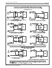
SPARK
MV
MV/PV
PV
GND
24V(GR)
24V
TH-W
MV
SPARK
1
2
3
4
5
6
7
8
9
W W
B B
R R
LO HI
MV
C
PV
HI
PilotBurnerWith
SparkElectrode
Sensor
RemoteFlameSensor
HighAltitude
(Optional)
Two-Stage
Aquastat
Two-Stage
GasValve
HWVR8304
Switch
Safety
Roll-Out
Blocked
Vent
Safety
Switch
SpaceHeating
Pump
(FieldSupplied)
Receptacle
Damper
Vent
Receptacle
Venter
Power
Jumper
RWR
A
Zone
Pump
Relay
Zone
Pump
Relay
Field
Thermostat
Supplied
Limit
HighOptional
Aquastat
TerminalTerminal
Boiler Boiler
Terminal
Boiler
Fuse
115V
24V
3
Relay
Pump
Zone
110V
Hot
110V
Neutral
1
4
6
Zone
Pump
Relay
IgnitionControl
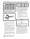
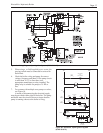
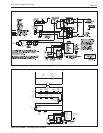
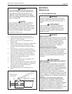
Figure 9e. Wiring Diagram, Spark Ignition, Two-Stage (BJVS 100-225).
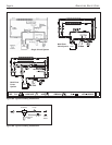
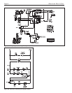
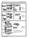
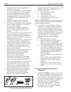
Figure 9f. Schematic, Two-Stage (BJVS 100-225).