


Brute Mini Hydronic Boiler
Page 17
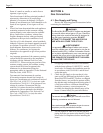
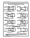
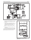
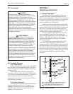
Figure 9a. Wiring Diagram, Spark Ignition System (BJVS 50 & 75).
Switch
Safety
Roll-Out
Blocked
Vent
Safety
Switch
SpaceHeating
Pump
(FieldSupplied)
Receptacle
Damper
Vent
Receptacle
Venter
Power
Jumper
RWR
A
Zone
Pump
Relay
Zone
Pump
Relay
Field
Thermostat
Supplied
Limit
HighOptional
Aquastat
TerminalTerminal
Boiler Boiler
Terminal
Boiler
Fuse
115V
24V
3
Relay
Pump
Zone
110V
Hot
110V
Neutral
1
4
6
Zone
Pump
Relay
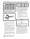
632145
24V PV PV MV GND GND
MV/ 24V
IgnitionControl
SPARK
PV
PV
MV/ MV
GasValve
HWVR8304
RemoteFlameSensor
HighAltitude(Optional)
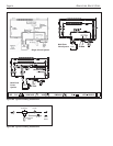
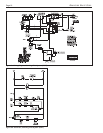
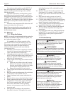
Figure 9b. Schematic, Spark Ignition System
(BJVS 50 & 75).
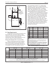
5. When using a or field supplied power venter, the
proving switch must be connected in series with
the hi-limit.
6. Check the boiler wiring and pump for correct
voltage, frequency and phase. If the pump circuit
is other than 115V, be sure there is an
appropriate transformer or relay installed. The
pump relay is suitable for pumps of ¾ HP or
less.
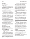
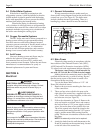
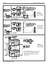
7. For systems with multiple zone pumps or valves,
see Figure 10.
A means of disconnecting the electrical supply
must be provided within sight of the boiler. The pump
and boiler must be wired as shown to insure that the
pump is running whenever the boiler is firing.